Photorefractive effect in LN: Theoretical part Weiwen Zou May 16,2003


53 Slides748.50 KB
Photorefractive effect in LN: Theoretical part Weiwen Zou May 16,2003
My view on the research 1. Microscopic changes: In different non-stoichiometric crystals without or with different doping concentration – Defects (Intrinsic and extrinsic) The gating ratio – Impurity levels in the gap of crystal Absorption change – Which location in lattice Sensitivity – 2. Macroscopic performances (change): M#(M number) Dynamic range Dark decay Optical quality . 2
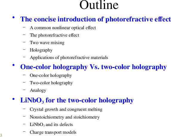
Outline The concise introduction of photorefractive effect – A common nonlinear optical effect – The photorefractive effect – Two wave mixing – Holography – Applications of photorefractive materials One-color holography Vs. two-color holography – One-color holography – Two-color holography – Analogy LiNbO3 for the two-color holography – Crystal growth and congruent melting – Nonstoichiometry and stoichiometry 3 – LiNbO3 and its defects – Charge transport models
Outline The performance change of the crystal due to doping – Defect changes due to varying dopants – Intrinsic defects – Extrinsic defects – Relative sequence Next plan – Experiments of two-color holography (part II) 4 The two-color holography’s parameters Determination methods and the corresponding precautions for them Setup of the experiment Doubly doped by Manganese(Mn) and Iron (Fe) (Nature,1998) Doped by Indium (In) Doped by Magnesium (Mg)
The concise introduction of photorefractive effect A common nonlinear optical effect The photorefractive effect Two wave mixing Holography Applications of photorefractive materials 5
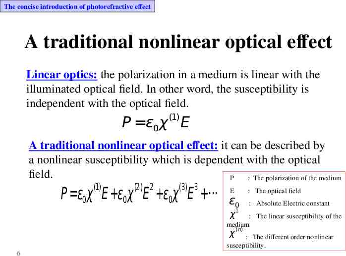
The concise introduction of photorefractive effect A traditional nonlinear optical effect Linear optics: the polarization in a medium is linear with the illuminated optical field. In other word, the susceptibility is independent with the optical field. (1) P ε0 χ E A traditional nonlinear optical effect: it can be described by a nonlinear susceptibility which is dependent with the optical field. P : The polarization of the medium (1) (2) 2 (3) 3 P ε0χ E ε0χ E ε0χ E E ε0 1 : The optical field : Absolute Electric constant χ : The linear susceptibility of the medium χ (n) : The different order nonlinear susceptibility. 6
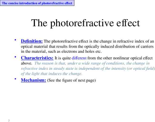
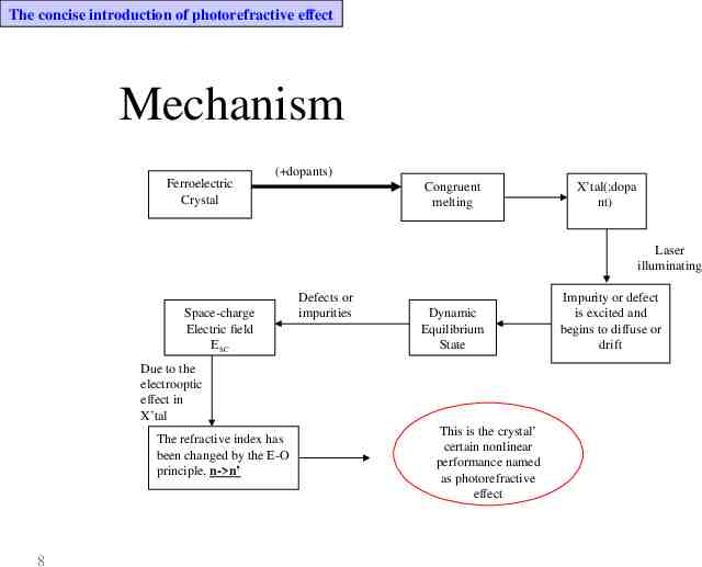
The concise introduction of photorefractive effect The photorefractive effect Definition: The photorefractive effect is the change in refractive index of an optical material that results from the optically induced distribution of carriers in the material, such as electrons and holes etc. Characteristics: It is quite different from the other nonlinear optical effect above. The reason is that, under a wide range of conditions, the change in refractive index in steady state is independent of the intensity (or optical field) of the light that induces the change. Mechanism: (See the figure of next page) 7
The concise introduction of photorefractive effect Mechanism Ferroelectric Crystal ( dopants) Congruent melting X’tal(:dopa nt) Laser illuminating Space-charge Electric field ESC Defects or impurities Dynamic Equilibrium State Due to the electrooptic effect in X’tal The refractive index has been changed by the E-O principle. n- n’ 8 This is the crystal’ certain nonlinear performance named as photorefractive effect Impurity or defect is excited and begins to diffuse or drift
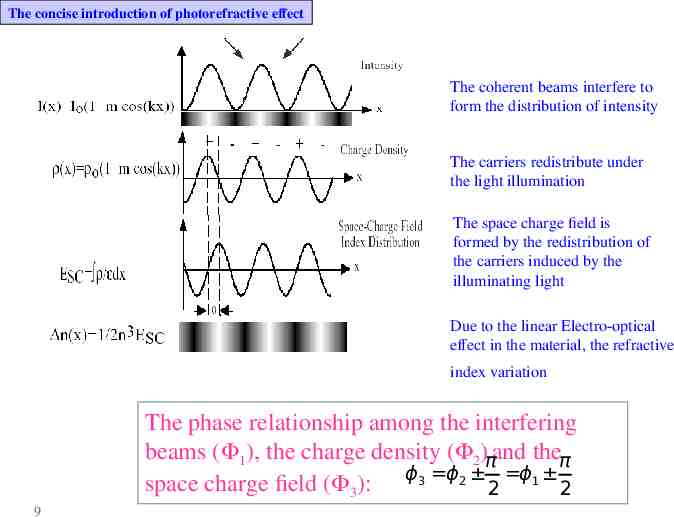
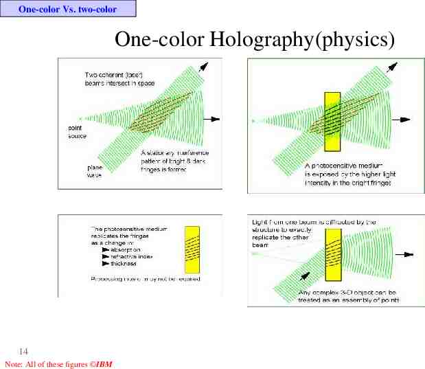
The concise introduction of photorefractive effect The coherent beams interfere to form the distribution of intensity The carriers redistribute under the light illumination The space charge field is formed by the redistribution of the carriers induced by the illuminating light Due to the linear Electro-optical effect in the material, the refractive index variation The phase relationship among the interfering beams ( 1), the charge density ( 2)πand theπ space charge field ( 3): ϕ3 ϕ2 2 ϕ1 2 9
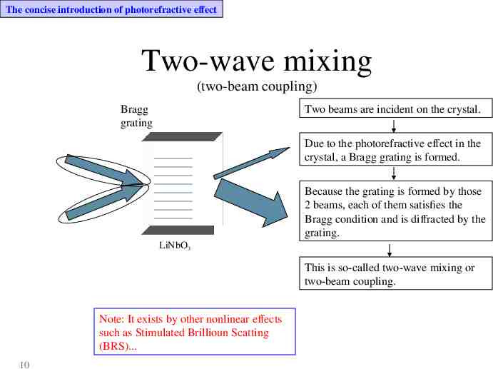
The concise introduction of photorefractive effect Two-wave mixing (two-beam coupling) Bragg grating Two beams are incident on the crystal. Due to the photorefractive effect in the crystal, a Bragg grating is formed. Because the grating is formed by those 2 beams, each of them satisfies the Bragg condition and is diffracted by the grating. LiNbO3 This is so-called two-wave mixing or two-beam coupling. Note: It exists by other nonlinear effects such as Stimulated Brillioun Scatting (BRS). 10
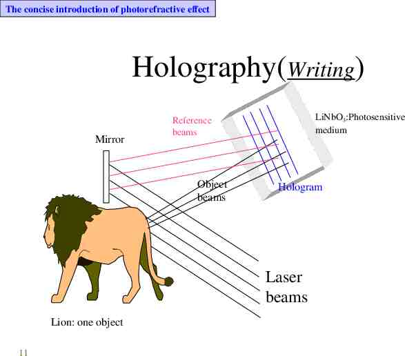
The concise introduction of photorefractive effect Holography(Writing) Mirror LiNbO3:Photosensitive medium Reference beams Object beams Hologram Laser beams Lion: one object 11
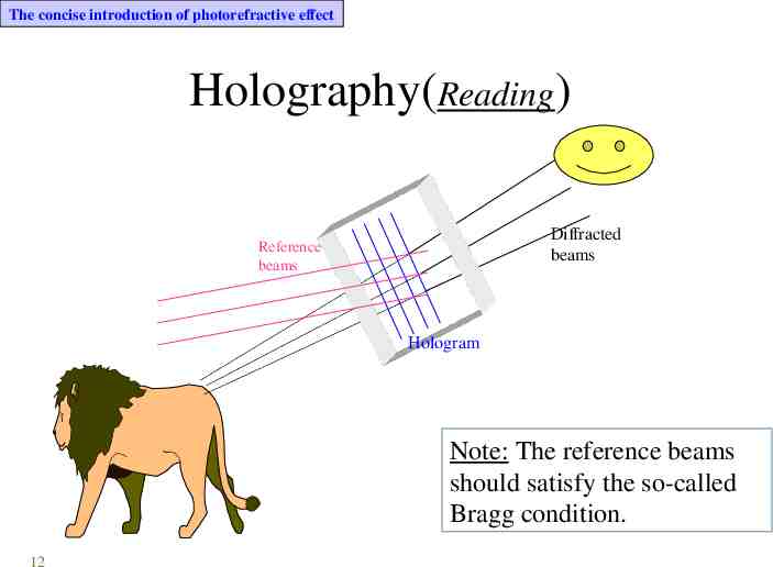
The concise introduction of photorefractive effect Holography(Reading) Diffracted beams Reference beams Hologram Note: The reference beams should satisfy the so-called Bragg condition. 12
One-color holography Vs. two-color holography One-color holography Two-color holography Analogy 13
One-color Vs. two-color One-color Holography(physics) 14 Note: All of these figures IBM
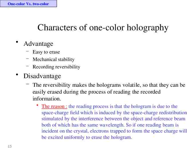
One-color Vs. two-color Characters of one-color holography Advantage – Easy to erase – Mechanical stability – Recording reversibility Disadvantage – The reversibility makes the holograms volatile, so that they can be easily erased during the process of reading the recorded information. The reason : the reading process is that the hologram is due to the space-charge field which is induced by the space-charge redistribution stimulated by the interference between the object and reference beam both of which has the same wavelength. So if one reading beam is incident on the crystal, electrons trapped to form the space charge will be excited uniformly to erase the hologram. 15
One-color Vs. two-color The ways to solve the disadvantage Thermal fixing Electrical fixing Two-wavelength fixing (2-color holography or “photogated” recording) 16
One-color Vs. two-color Thermal fixing Mechanism(copy the space-charge pattern into a pattern of immobile ions): A copy of the stored index gratings is made by thermally activating proton diffusion, which creates an optically stable complementary proton grating to store the hologram. Disadvantages – Long time for fixing – Not easy for erosion. 17
One-color Vs. two-color Electrical fixing Mechanism(copy space-charge pattern into felloelectric domains) Disadvantage – Not easy for erosion. 18
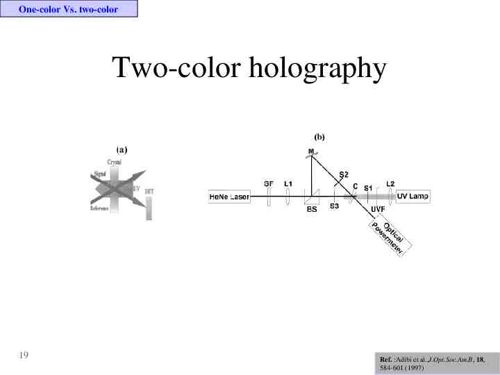
One-color Vs. two-color Two-color holography 19 Ref. :Adibi et al.,J.Opt.Soc.Am.B, 18, 584-601 (1997)
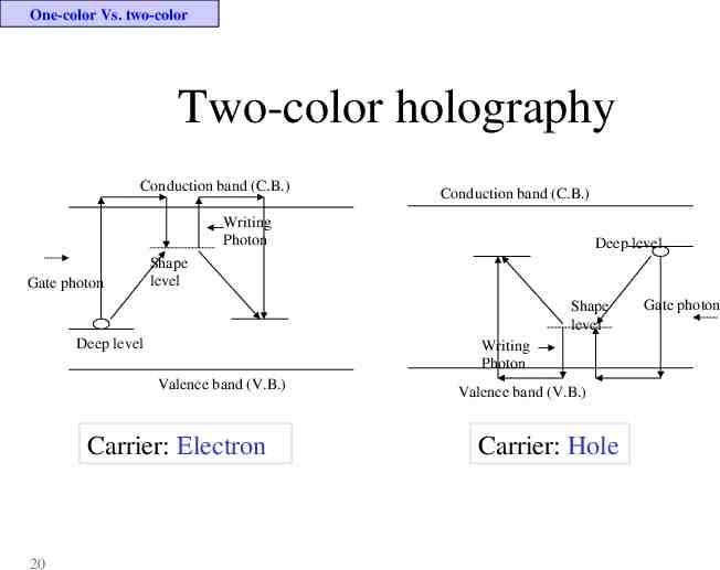
One-color Vs. two-color Two-color holography Conduction band (C.B.) Conduction band (C.B.) Writing Photon Gate photon Deep level Shape level Shape level Deep level Writing Photon Valence band (V.B.) Carrier: Electron 20 Valence band (V.B.) Carrier: Hole Gate photon
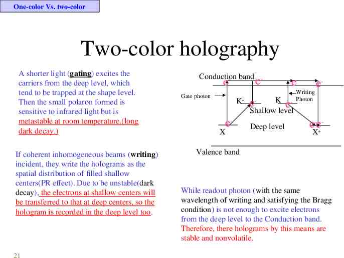
One-color Vs. two-color Two-color holography A shorter light (gating) excites the carriers from the deep level, which tend to be trapped at the shape level. Then the small polaron formed is sensitive to infrared light but is metastable at room temperature.(long dark decay.) If coherent inhomogeneous beams (writing) incident, they write the holograms as the spatial distribution of filled shallow centers(PR effect). Due to be unstable(dark decay), the electrons at shallow centers will be transferred to that at deep centers, so the hologram is recorded in the deep level too. 21 Conduction - band e- e Gate photon K e- X eWriting - Photon e- K e Shallow level e- Deep level e-eX Valence band While readout photon (with the same wavelength of writing and satisfying the Bragg condition) is not enough to excite electrons from the deep level to the Conduction band. Therefore, there holograms by this means are stable and nonvolatile.
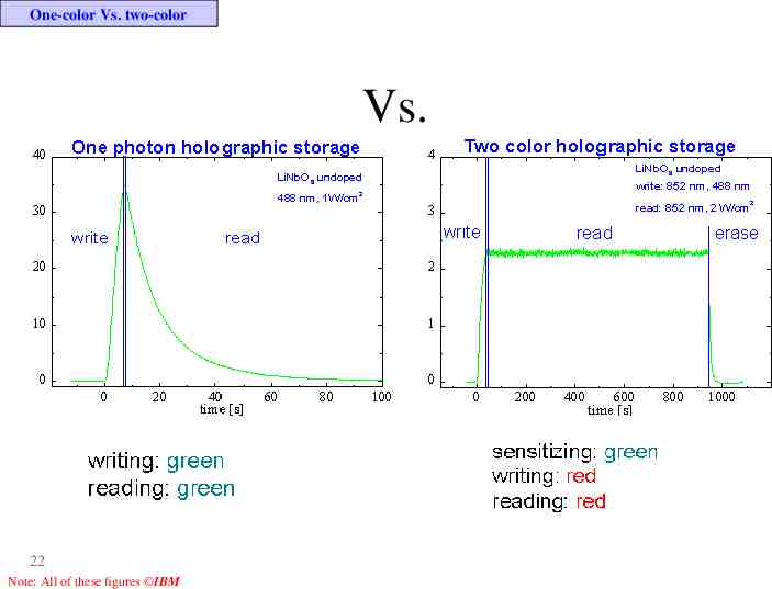
One-color Vs. two-color Vs. 22 Note: All of these figures IBM
LiNbO3 for the two-color holography Crystal growth and congruent melting Non-stoichiometry vs. stoichiometry LiNbO3 intrinsic defects Charge transport models 23
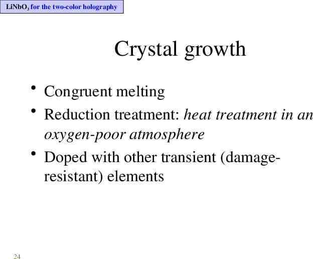
LiNbO3 for the two-color holography Crystal growth Congruent melting Reduction treatment: heat treatment in an oxygen-poor atmosphere Doped with other transient (damageresistant) elements 24
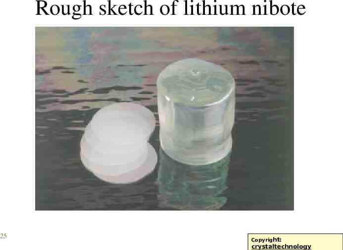
Rough sketch of lithium nibote 25 Copyright: Copyright: crystaltechnology
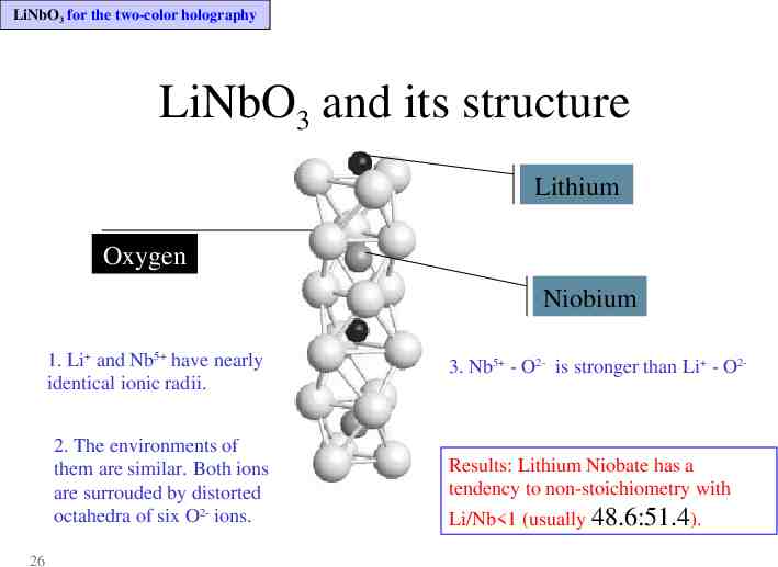
LiNbO3 for the two-color holography LiNbO3 and its structure Lithium Oxygen Niobium 1. Li and Nb5 have nearly identical ionic radii. 2. The environments of them are similar. Both ions are surrouded by distorted octahedra of six O2- ions. 26 3. Nb5 - O2- is stronger than Li - O2- Results: Lithium Niobate has a tendency to non-stoichiometry with Li/Nb 1 (usually 48.6:51.4).
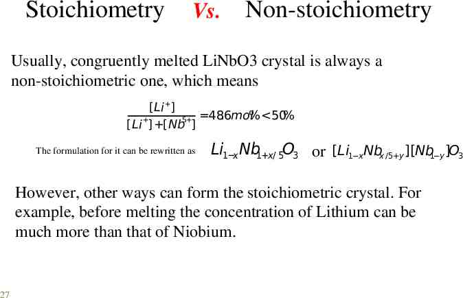
Stoichiometry Vs. Non-stoichiometry Usually, congruently melted LiNbO3 crystal is always a non-stoichiometric one, which means [Li ] % 50% 5 48.6mol [Li ] [Nb ] The formulation for it can be rewritten as Li1 x Nb1 x/ 5O3 or [Li1 xNbx /5 y ][Nb1 y ]O3 However, other ways can form the stoichiometric crystal. For example, before melting the concentration of Lithium can be much more than that of Niobium. 27
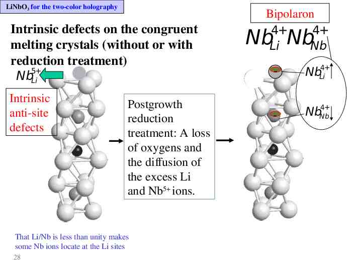
LiNbO3 for the two-color holography Intrinsic defects on the congruent melting crystals (without or with reduction treatment) Nb5 Li Intrinsic anti-site defects Postgrowth reduction treatment: A loss of oxygens and the diffusion of the excess Li and Nb5 ions. That Li/Nb is less than unity makes some Nb ions locate at the Li sites 28 Bipolaron 4 4 Li Nb Nb Nb 4 - NbLi - 4 NbNb
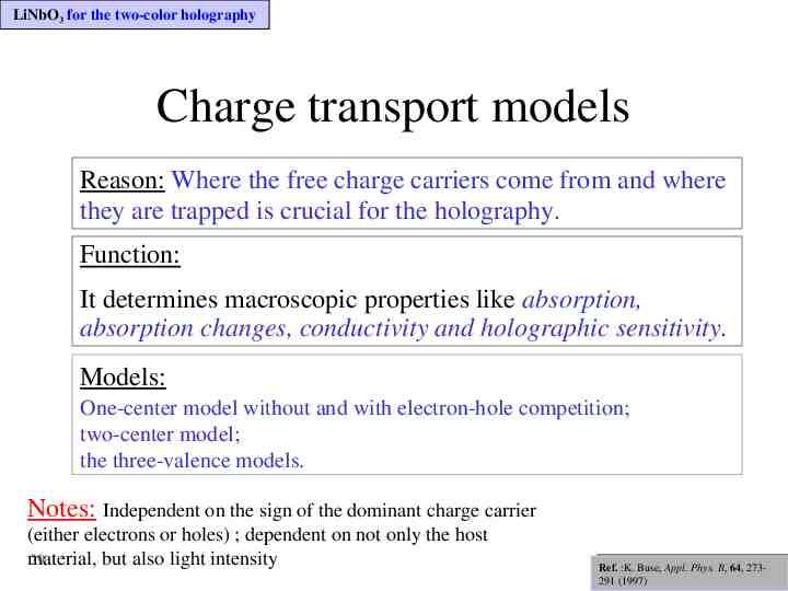
LiNbO3 for the two-color holography Charge transport models Reason: Where the free charge carriers come from and where they are trapped is crucial for the holography. Function: It determines macroscopic properties like absorption, absorption changes, conductivity and holographic sensitivity. Models: One-center model without and with electron-hole competition; two-center model; the three-valence models. Notes: Independent on the sign of the dominant charge carrier (either electrons or holes) ; dependent on not only the host 29 material, but also light intensity Ref: Phys. B, Ref. :K.K.Buse, Buse, Appl.Appl. Phys. B, 64, 273Ref: K.Buse, Appl. Phys. B, 64,1997 291 (1997) 64,1997
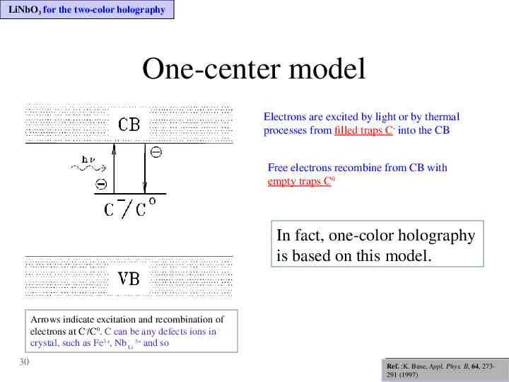
LiNbO3 for the two-color holography One-center model Electrons are excited by light or by thermal processes from filled traps C- into the CB Free electrons recombine from CB with empty traps C0 In fact, one-color holography is based on this model. Arrows indicate excitation and recombination of electrons at C-/C0. C can be any defects ions in crystal, such as Fe3 , Nb Li 5 and so 30 Ref: Phys. B, Ref. :K.K.Buse, Buse, Appl.Appl. Phys. 64, 273Ref: K.Buse, Appl.B,Phys. B, 64,1997 291 (1997) 64,1997
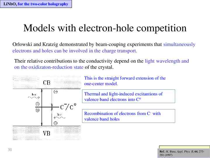
LiNbO3 for the two-color holography Models with electron-hole competition Orlowski and Kratzig demonstrated by beam-couping experiments that simultaneously electrons and holes can be involved in the charge transport. Their relative contributions to the conductivity depend on the light wavelength and on the oxidizaton-reduction state of the crystal. This is the straight forward extension of the one-center model. Thermal and light-induced excitantions of valence band electrons into C0 Recombination of electrons from C- with valence band holes 31 Ref: and B, Kratzig Ref. :K.Orlowski Buse, Appl. Phys. 64, 273- , , Ref: Orlowski and Kratzig Solid state commun. 291 (1997) Solid state commun.
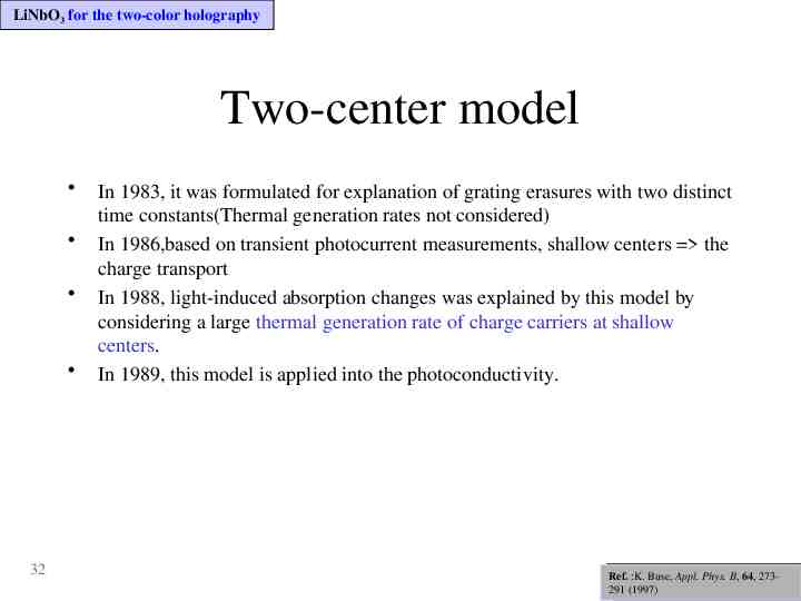
LiNbO3 for the two-color holography Two-center model 32 In 1983, it was formulated for explanation of grating erasures with two distinct time constants(Thermal generation rates not considered) In 1986,based on transient photocurrent measurements, shallow centers the charge transport In 1988, light-induced absorption changes was explained by this model by considering a large thermal generation rate of charge carriers at shallow centers. In 1989, this model is applied into the photoconductivity. Ref: Phys. B, Ref. :K.K.Buse, Buse, Appl.Appl. Phys. 64, 273Ref: K.Buse, Appl.B,Phys. B, 64,1997 291 (1997) 64,1997
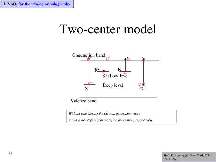
LiNbO3 for the two-color holography Two-center model Conduction - band e- e K e- X e- e- K e Shallow level e- Deep level e-eX Valence band Without considering the thermal generation rates X and K are different photorefractive centers, respectively. 33 Ref. :K. Buse, Appl. Phys. B, 64, 273291 (1997)
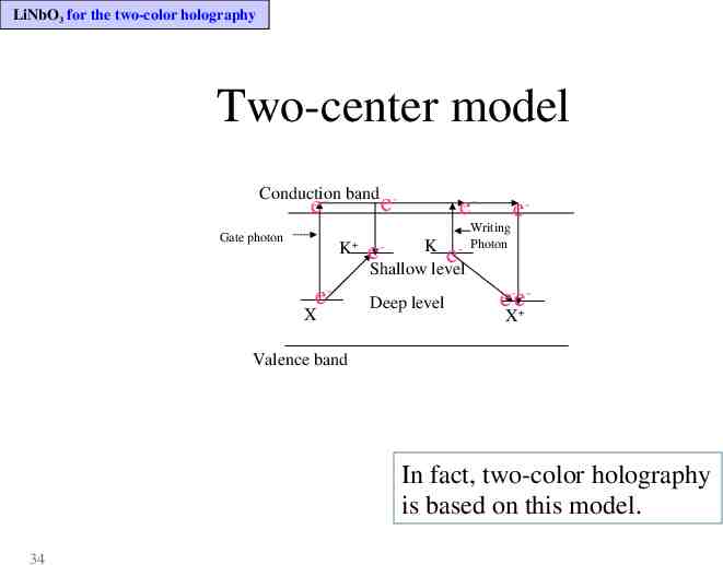
LiNbO3 for the two-color holography Two-center model Conduction - band e- e Gate photon K e- X eWriting - Photon e- K e Shallow level e- Deep level e-eX Valence band In fact, two-color holography is based on this model. 34
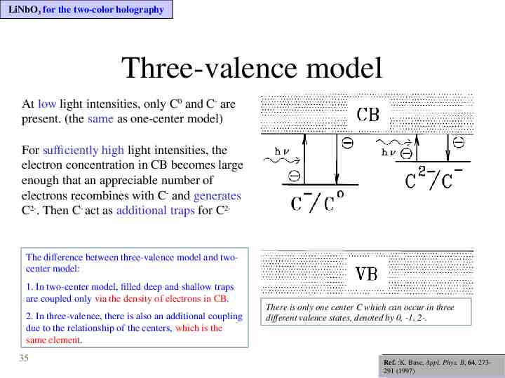
LiNbO3 for the two-color holography Three-valence model At low light intensities, only C0 and C- are present. (the same as one-center model) For sufficiently high light intensities, the electron concentration in CB becomes large enough that an appreciable number of electrons recombines with C- and generates C2-. Then C- act as additional traps for C2- The difference between three-valence model and twocenter model: 1. In two-center model, filled deep and shallow traps are coupled only via the density of electrons in CB. 2. In three-valence, there is also an additional coupling due to the relationship of the centers, which is the same element. 35 There is only one center C which can occur in three different valence states, denoted by 0, -1, 2-. Ref: Phys. B, Ref. :K.K.Buse, Buse, Appl.Appl. Phys. 64, 273Ref: K.Buse, Appl.B,Phys. B, 64,1997 291 (1997) 64,1997
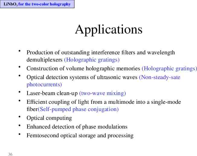
LiNbO3 for the two-color holography Applications Production of outstanding interference filters and wavelength demultiplexers (Holographic gratings) Construction of volume holographic memories (Holographic gratings) Optical detection systems of ultrasonic waves (Non-steady-sate photocurrents) Laser-beam clean-up (two-wave mixing) Efficient coupling of light from a multimode into a single-mode fiber(Self-pumped phase conjugation) Optical computing Enhanced detection of phase modulations Femtosecond optical storage and processing 36
The performance change of the crystal due to doping Defect Changes due to varying dopants Intrinsic defects Extrinsic defects Relative sequence 37
The performance change due to doping Defect changes by the doping procedure 38 When a certain element is doped into the non-stoichiometric LN, the impurity ion enters into the sites so that the concentration of the intrinsic defects decrease, which is formed by the non-stoichiometric composition. If the concentration of the impurity ions exceed the so-called optical-damage threshold value, all the intrinsic defects are almost displaced by the impurities. It results that the absorption band by the intrinsic defects is shifted owning to the new-formed defects.
The performance change due to doping The importance of defects Deferent configuration (or formulation) of one crystal with different defects will have different holographic performance according to its mechanism. 39
The performance change due to doping Intrinsic defects O- trapped holes (Cation vacancy) Nb4 small polaron (An electron self-trapped at Nb orNb Bipolarons (Nb Nb :diamagnetic pairs of electrons trapped at Nb Nb 4 4 Li NbNb5 NbLi5 complex) Oxygen Vacancies (VO) 40 5 5 Li )
The performance change due to doping Extrinsic defects Magnesium (Mg) Iron(Fe) Further extrinsic defects 41
The performance change due to doping Cation vacancy: O- trapped holes Form: by capturing a defect electron(hole) at one of the neighboring O2- , local charge compensation can be achieved under ionizing radiation Evidence: – ESR(electron spin resonance) of congruent Lithium niobate by twophoton X- and by e--irradiation. It consists of several overlapping lines, which cannot be disentangled, due to unresolved Li and Nb hyperfine interaction. – Optical absorption band: peak at 2.5ev (approximate 0.495um). It is caused by the light induced transfer of the hole from its original trapping site to an equivalent O2- ions around the defect (like a small polaron). – The Dark decay dynamics of the absorption coeffeicent change. (Pro. Tomita’ Group) 42 Ref.: O.F.Schirmer et. al.,J.Phys. Chem.Solids, 52, 185-200 (1991)
The performance change due to doping Cation vacancy: O- trapped holes Temperature dependence of the X-ray-induced O- coloration: – In the 50-200 K range, decaying at the same rate as the absorption due to Nb4 , the ioniztion energy of which: 0.54ev – In 100-200K, using isochronal annealing, optical absorption and ESR decay simultaneously. – In about 15K, X-irradiation in LN doped with 9% Mg, no trapped holes are formed; with 6% Mg the concentration is rather low. In Mg-doped crystal, the electron trapping energy is much less than in undoped crystals. The Nb4 electrons recombine with O- at rather low temperature. The concentration of cation vacancies rises with decreasing [Li]/[Nb], whereas self-trapping of holes cannot be excluded for high [Li]/[Nb]. 43 Ref.: O.F.Schirmer et. al.,J.Phys. Chem.Solids, 52, 185-200 (1991)
The performance change due to doping Small polarons Evidence: – A characteristic 10-line pattern by two-photon (2*2.46ev) and Xirradiation of congruent undoped LN, which is caused by hyperfine interaction with the nucleus of 93Nb (the only stable isotope of Nb) – In reduced undoped LN after illumination with light of wavelength 600nm at T 80K, the same ESR was found. Before illumination, peak at approximate 2.5ev(500nm) due to bipolarons After illumination, 1.6ev (760nm) attributed to small polarons and the low energy party of the band explained by small polaron absoption based on Form: an electron self-trapped at a NbLi5 ion to a free small polaron. (1.6 ev) 44 Ref.: O.F.Schirmer et. al.,J.Phys. Chem.Solids, 52, 185-200 (1991)
The performance change due to doping Bipolarons (Electron pairs trapped at NbLi-NbNb) Form: Electron pairs trapped at NbLi-NbNb Evidence: – In reduced undoped LN after illumination with light of wavelength 600nm at T 80K, the same ESR was found. Before illumination, peak at approximate 2.5ev(500nm) due to bipolarons After illumination, 1.6ev (760nm) attributed to small polarons The reduced crystal is diamagnetic and no ESR signal accompanying the absorption band the absorption at 2.5ev not due to small polarons and oxygen trapped holes Characteristics: 45 – Dissociation: By heating or light illumination, a transfer of one of the paired electrons out of the cluster. – The efficiency of coloration by reducing the [Li]/[Nb] ratio: raising the ration decreases the coloration. (because only in strongly non-stoichiometric crystals is a sufficient number of sites for electrons trapped after O left the crystal.) Ref.: O.F.Schirmer et. al.,J.Phys. Chem.Solids, 52, 185-200 (1991)
The performance change due to doping Magnesium (Mg) General comment: its properties is strongly related to those of the intrinsic defects Evidence: – 4.6mol% MgO compared with a lower Mg concentration, the effect for reducing the optical damage is much strongly. – A distinct threshold at a critical Mg concentration: [Mg] c 4.5mol%. – The effect due to the Mg concentration bigger than critical value (not deliberately doped with Fe) The optical absorption in reduced crystals (due to intrinsic defects) decreases The intensity of X-ray-induced luminescence increases by several orders of magnitude while other related properties, such as width and energy of the band, also change abruptly. The absorption edge shows a blueshift The X-ray-induced Nb4 ESR intensity decreases to zero. – Codoped with Fe and Mg, the photoconductivity increases and the photovoltaic effect is not be effected 46 Ref.: O.F.Schirmer et. al.,J.Phys. Chem.Solids, 52, 185-200 (1991)
The performance change due to doping Magnesium (Mg) Similarity: The features for high [Li]/[Nb] are similar to those for low [Li]/[Nb] but with high [Mg] doping. – All of those experiment results for high [Li]/[Nb] are the same as those of high doping. – With [Mg] fixed and the ratio of [Li]/[Nb] varying, the threshold for the change of properties is influenced by the ratio. Function: For Mg only indirectly influences the behavior of the specimens investigated, the function of Mg doping is to replace the NbLi. 47 Ref.: O.F.Schirmer et. al.,J.Phys. Chem.Solids, 52, 185-200 (1991)
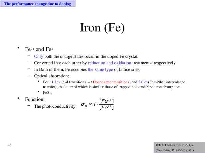
The performance change due to doping Iron (Fe) Fe2 and Fe3 – – – – Only both the charge states occur in the doped Fe crystal. Converted into each other by reduction and oxidation treatments, respectively In Both of them, Fe occupies the same type of lattice sites. Optical absorption: Fe2 : 1.1ev (d-d transitions -- Donor state transitions) and 2.6 ev(Fe2 -Nb5 intervalence transfer), the latter of which is similar those of trapped hole and bipolaron absorption. Fe3 : 48 Function: [Fe2 ] – The photoconductivity: σ p I 3 [Fe ] Ref.: O.F.Schirmer et. al.,J.Phys. Chem.Solids, 52, 185-200 (1991)
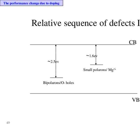
The performance change due to doping Relative sequence of defects I CB 2.5ev 1.6ev Small polarons/ Mg2 Bipolarons/O- holes VB 49
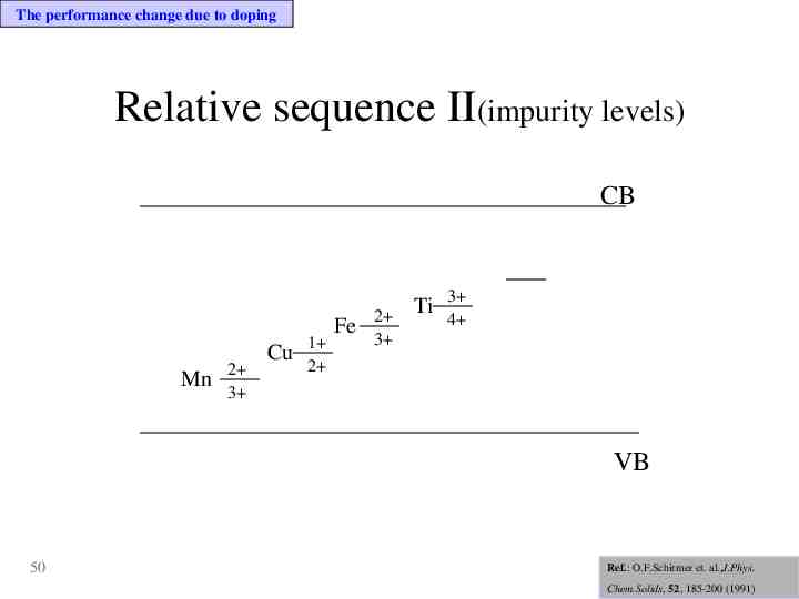
The performance change due to doping Relative sequence II(impurity levels) CB Mn 2 3 Cu 1 2 Fe 2 3 Ti 3 4 VB 50 Ref.: O.F.Schirmer et. al.,J.Phys. Chem.Solids, 52, 185-200 (1991)
The performance change due to doping Interrelation between intrinsic and extrinsic defects Any possible manipulations with dopants induce change in the subsystem of intrinsic defects and, by their common influence cause variations of the properties of LN Because of the high concentration of intrinsic defects, the conventional congruent crystals are tolerant to impurities substituting for Li or Nb ions There are different complexes, such as “impurity ion-intrinsic defect” or “impurity-impurity” and so on, due to the variation and the concentration of the dopants The strong coupling of extrinsic and intrinsic defects is one of the most important features of LN, which is indeed rather flexible and very sensitive to changes in both defects. 51 Ref.: G.Malovichko et.al.Appl. Phys. B, 68, 785-793 (1997)
Next plan Experiments of two-color holography – The two-color holography’s parameters – Determination methods and the corresponding precautions for them – Setup of the experiment – Doubly doped by Manganese(Mn) and Iron (Fe) (Nature,1998) – Doped by Indium (In) – Doped by Magnesium (Mg) (The main topic in our group) 52
53