Permanent-magnet helicon sources for etching, coating, and


41 Slides7.65 MB
Permanent-magnet helicon sources for etching, coating, and thrust Francis F. Chen, UCLA Low Temperature Plasma Teleseminar, June 14, 2013; originally prepared for (but not given at): 2013 Workshop on Radiofrequency Discharges, La Badine, La Presqu’ile de Giens, France, 29-31 May 2013
Helicons are RF plasmas in a magnetic field Density increase over ICP Prf 200 400 600 800 1000 % 16% 21% 35% 38% 42% UCLA
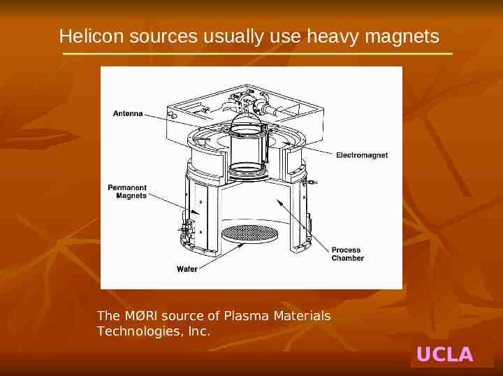
Helicon sources usually use heavy magnets The MØRI source of Plasma Materials Technologies, Inc. UCLA
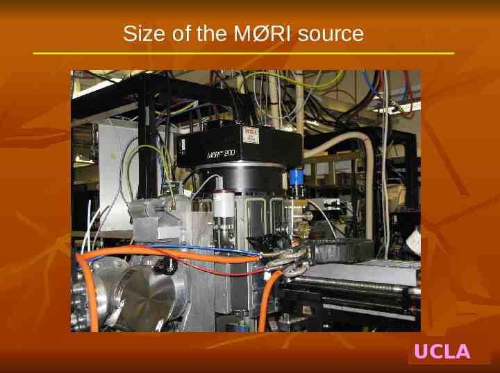
Size of the MØRI source UCLA
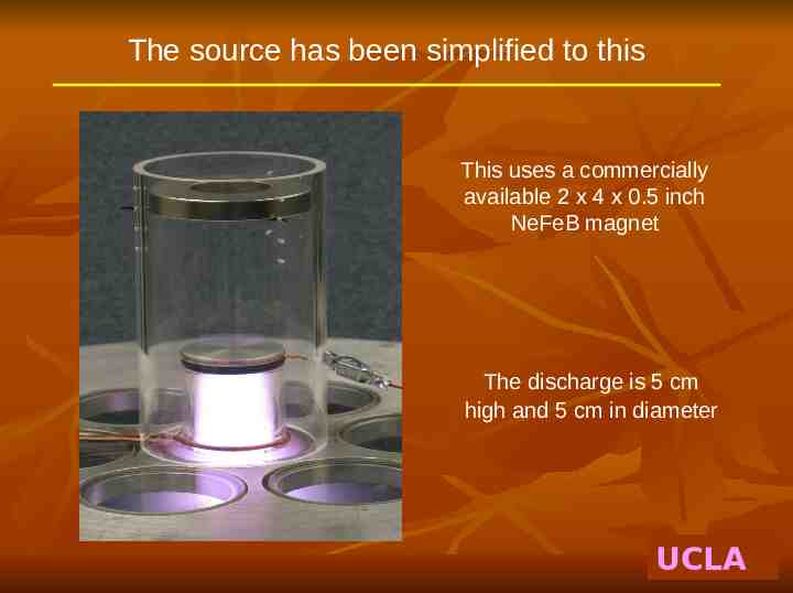
The source has been simplified to this This uses a commercially available 2 x 4 x 0.5 inch NeFeB magnet The discharge is 5 cm high and 5 cm in diameter UCLA
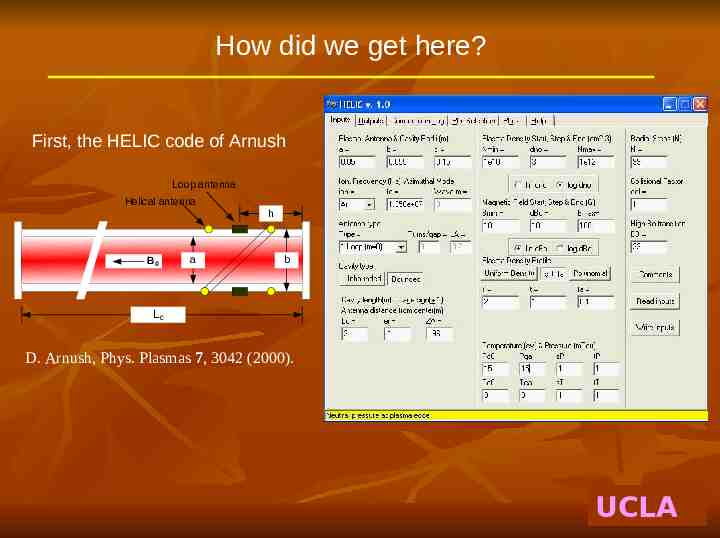
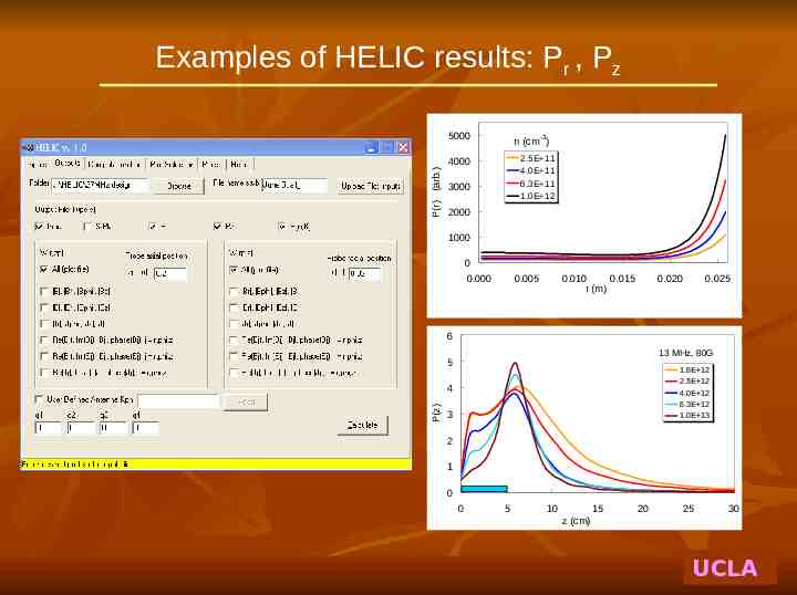
How did we get here? First, the HELIC code of Arnush Loop antenna Helical antenna B0 a h b Lc D. Arnush, Phys. Plasmas 7, 3042 (2000). UCLA
Examples of HELIC results: Pr , Pz 5000 -3 n (cm ) 2.5E 11 4.0E 11 6.3E 11 1.0E 12 P(r) (arb.) 4000 3000 2000 1000 0 0.000 0.005 0.010 0.015 r (m) 0.020 0.025 6 13 MHz, 80G 5 1.6E 12 2.5E 12 4.0E 12 6.3E 12 1.0E 13 P(z) 4 3 2 1 0 0 5 10 15 20 25 30 z (cm) UCLA
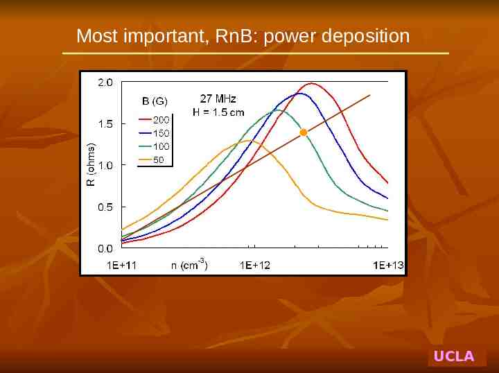
Most important, RnB: power deposition UCLA
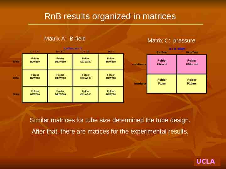
RnB results organized in matrices Matrix A: B-field D 7.4" 1 mTorr, ei -1 D 11" D 13" Matrix C: pressure 100W Folder D7W100 Folder D11W100 Folder D13W100 Folder D0W100 300W Folder D7W300 Folder D11W300 Folder D13W300 Folder D0W300 500W Folder D7W500 Folder D11W500 Folder D13W500 D 0, 300W D 0 1 mTorr 10 mTorr conductor Folder P1cond Folder P10cond insulator Folder P1ins Folder P10ins Folder D0W500 Similar matrices for tube size determined the tube design. After that, there are matices for the experimental results. UCLA
Optimized discharge tube: 5 x 5 cm GAS INLET (optional) 1. Diameter: 2 inches 2. Height: 2 inches 3. Aluminum top 5 cm ANTENNA 4. Material: quartz 5. “Skirt” to prevent eddy currents canceling the antenna current 5.1 cm 10 cm The antenna is a simple loop, 3 turns for 13 MHz, 1 turn for 27 MHz. The antenna must be as close to the exit aperture as possible. Antenna: 1/8” diam tube, water-cooled UCLA
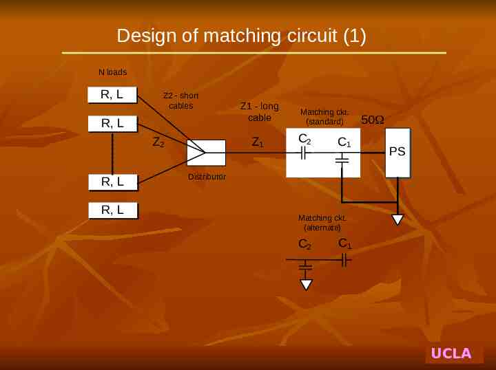
Design of matching circuit (1) N loads R, L Z2 - short cables R, L Z2 R, L R, L Z1 - long cable Z1 Matching ckt. (standard) C2 C1 50W PS Distributor Matching ckt. (alternate) C2 C1 UCLA
Design of 50 matching circuit (2) Let the load be RL jXL : R and X have first to be transformed by cable length k R0C, R0 50 UCLA
Forbidden regions of L, R, and Z (N 8) 2000 800 N N 8 6 4 2 1 1000 200 0 0 0.5 1 L (mH) 1.5 2 0 2.5 0.5 1 L (mH) 1600 2000 C1(S) C2(S) 1400 1200 C1(S) C2(S) 1500 1000 C (pF) C (pF) 400 500 0 8 6 4 2 1 600 C2 (pF) C1 (pF) 1500 800 1000 600 500 400 200 0 0 0 50 Z2 (cm) 100 150 200 0.5 1.5 2.5 R (ohms) 3.5 4.5 UCLA
Instead, we can use annular PMs 8 PM Permanent magnet 6 4 2 NdFeB ring magnet 3” ID, 5” OD, 1” high 0 -2 Stagnation point The far-field is fairly uniformhere Put plasma -4 -6 -8 -10 or here, to adjust Bfield -12 -14 -16 -10 -8 -6 -4 -2 0 2 4 6 8 10 UCLA
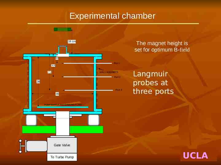
Experimental chamber 19 cm The magnet height is set for optimum B-field 6.8 Port 1 16.9 WALL MAGNETS 27.2 Port 2 38 Port 3 46 Langmuir probes at three ports PUMP BAFFLE AND GROUND PLANE Gate Valve To Turbo Pump UCLA
Optimization of the B-field Peak density in Port 2 vs. B and Prf @ 27 MHz 30-60 G is best UCLA
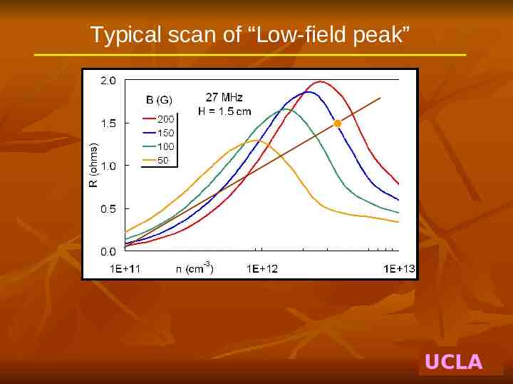
Typical scan of “Low-field peak” UCLA
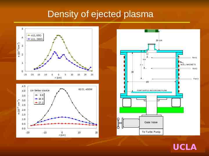
Density of ejected plasma 5 n11, 65G n11, 280G 19 cm 3 n (10 11 3 /cm ) 4 2 6.8 Port 1 16.9 1 WALL MAGNETS 27.2 Port 2 0 38 -25 -20 -15 -10 -5 0 5 10 15 20 25 r (cm) Port 3 46 4.5 -3 cm ) 11 PUMP BAFFLE AND GROUND PLANE 6.8 16.9 27.2 3.5 n (10 62 G, 400W cm below source 4.0 3.0 2.5 2.0 1.5 1.0 Gate Valve 0.5 0.0 -20 -10 0 r (cm) 10 20 To Turbo Pump UCLA
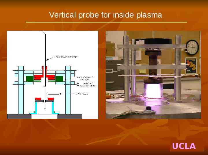
Vertical probe for inside plasma UCLA
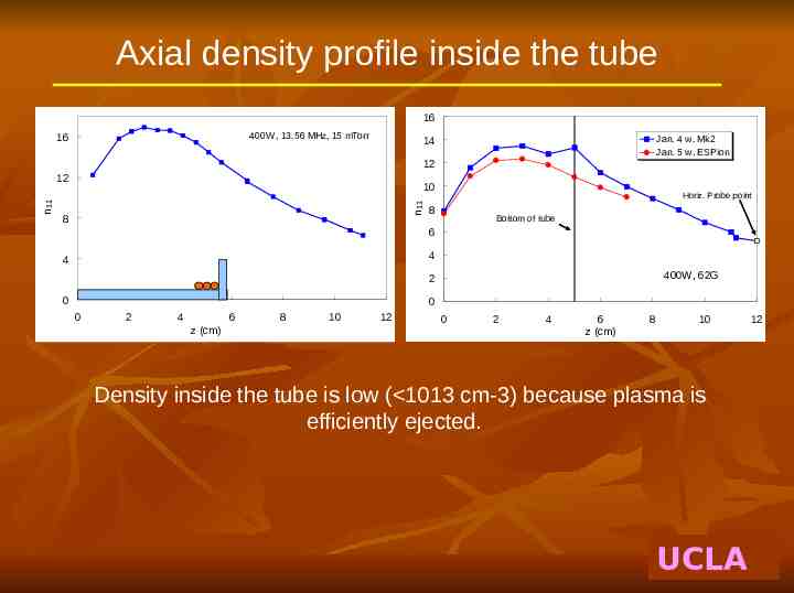
Axial density profile inside the tube 16 400W, 13.56 MHz, 15 mTorr 16 Jan. 4 w. Mk2 Jan. 5 w. ESPion 14 12 10 n11 n11 12 8 Horiz. Probe point 8 Bottom of tube 6 4 4 400W, 62G 2 0 0 0 2 4 6 z (cm) 8 10 12 0 2 4 6 z (cm) 8 10 Density inside the tube is low ( 1013 cm-3) because plasma is efficiently ejected. UCLA 12
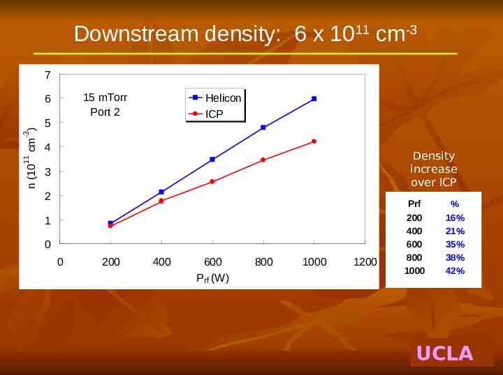
Downstream density: 6 x 1011 cm-3 7 15 mTorr Port 2 5 Helicon ICP -3 cm ) 6 4 n (10 11 Density increase over ICP 3 2 1 0 0 200 400 600 Prf (W) 800 1000 1200 Prf 200 400 600 800 1000 % 16% 21% 35% 38% 42% UCLA
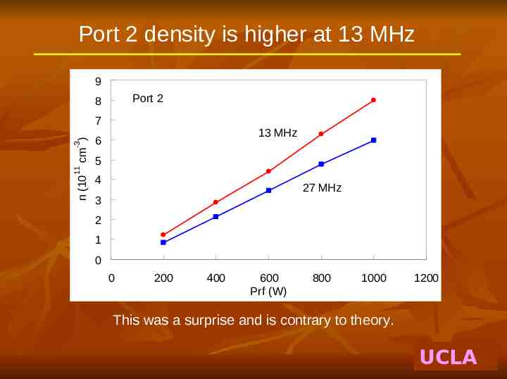
Port 2 density is higher at 13 MHz 9 Port 2 8 n (10 11 -3 cm ) 7 13 MHz 6 5 4 27 MHz 3 2 1 0 0 200 400 600 Prf (W) 800 1000 1200 This was a surprise and is contrary to theory. UCLA
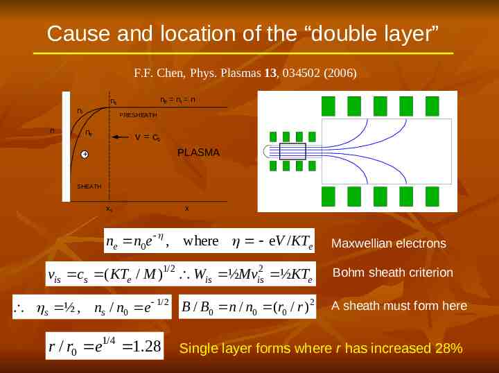
Cause and location of the “double layer” F.F. Chen, Phys. Plasmas 13, 034502 (2006) ne ni n ns ni n PRESHEATH ne v cs PLASMA SHEATH xs x ne n0e , where eV /KTe vis cs ( KTe / M )1/2 Wis ½Mvis2 ½KTe s ½ , ns / n0 e 1/2 B / B0 n / n0 (r0 / r ) 2 r / r0 e1/4 1.28 Maxwellian electrons Bohm sheath criterion A sheath must form here Single layer forms where r has increased 28%
Where a diffuse “double layer” would occur 250 B (G) 200 150 100 Approx. location of "double layer" 50 0 5 10 15 20 25 30 z (cm) UCLA
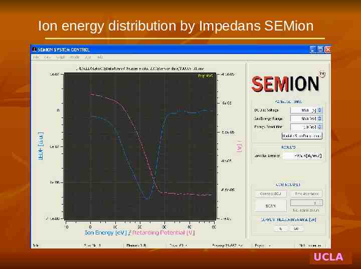
Ion energy distribution by Impedans SEMion UCLA
IEDFs vs. Prf in Port 1 2E-06 600W 500W 400W 400W repeat 300W 200W 100W Vs IEDF 2E-06 1E-06 5E-07 0E 00 0 5 10 V 15 20 25 30 UCLA
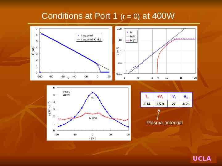
Conditions at Port 1 (r 0) at 400W 7 100 6 Ii squared Ii squared (OML) 10 Ie (mA) 4 3 2 1 0.1 1 0 -100 -80 -60 V -40 -20 0 20 0.01 -5 0 5 V 10 15 20 6 Port 1 400W -3 3 cm ) 4 11 5 n (10 2 I (mA) 2 5 Ie Ie(fit) Ie (0) n 11 2 Te eVs iVs n11 2.14 15.9 27 4.21 Te (eV) Plasma potential 1 0 -20 -10 0 r (cm) 10 20 UCLA
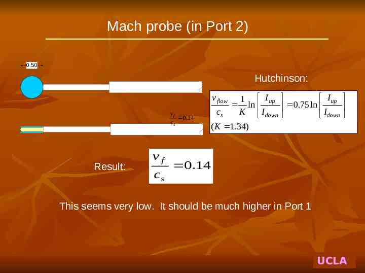
Mach probe (in Port 2) 0.50 Hutchinson: v flow vf cs Result: vf cs 0.14 Iup 1 Iup ln 0.75ln cs K I down I down ( K 1.34) 0.14 This seems very low. It should be much higher in Port 1 UCLA
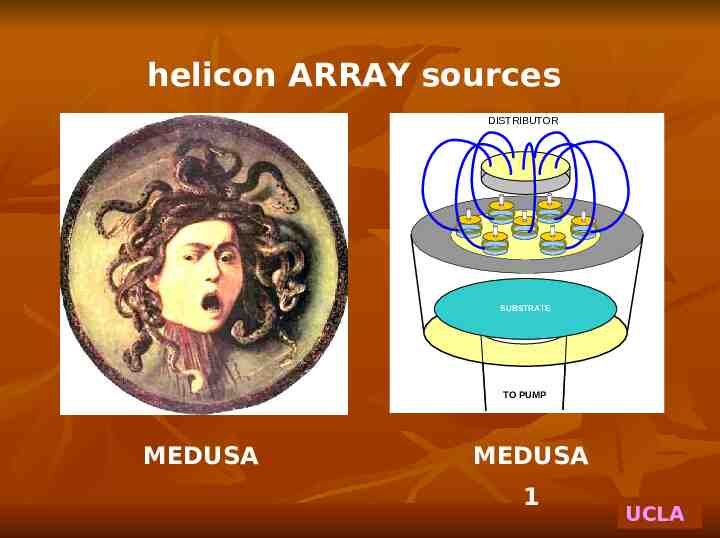
helicon ARRAY sources DISTRIBUTOR SUBSTRATE TO PUMP MEDUSA MEDUSA 1 UCLA
The Medusa 2 large-area array UCLA
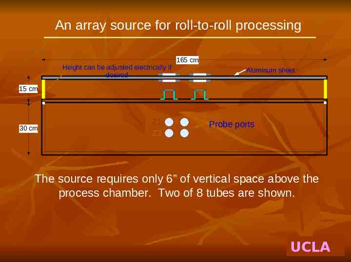
An array source for roll-to-roll processing Height can be adjusted electrically if desired 165 cm Aluminum sheet 15 cm 30 cm Z1 Z2 Probe ports The source requires only 6” of vertical space above the process chamber. Two of 8 tubes are shown. UCLA
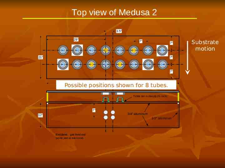
Top view of Medusa 2 3.5" 29" 7" 7" 21" 7" 7" 65" Possible positions shown for 8 tubes. Tubes set in deeply (½ inch) 7" 3/4” aluminum 12" 1/2" aluminum Endplates: gas feed and probe port at each end. Substrate motion
Two arrangements of the array 35.6 cm y x 53.3 cm 17.8 17.8 17.8 Staggered array Covers large area uniformly for substrates moving in the y-direction 165 cm Top view 53.3 cm y 17.8 x 17.8 17.8 17.8 165 cm Compact array Gives higher density, but uniformity suffers from end effects.
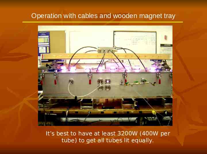
Operation with cables and wooden magnet tray It’s best to have at least 3200W (400W per tube) to get all tubes lit equally.
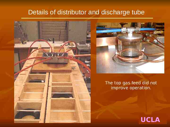
Details of distributor and discharge tube The top gas feed did not improve operation. UCLA
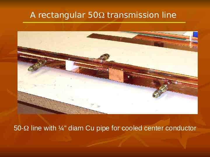
A rectangular 50 transmission line 50- line with ¼” diam Cu pipe for cooled center conductor
Operation with rectangular transmission line
Radial profile at Z2 across rows 3.5 3 n KTe -3 cm ) 2.5 n (10 11 2 1.5 1 0.5 0 -25 -20 -15 -10 -5 0 r (cm) 5 10 15 20 25
Density profiles with staggered array Staggered configuration, 2kW Bottom probe array 5 Staggered, 2kW, D 7", 20mTorr Argon n (1011 cm-3) 4 y (in.) -3.5 0 3.5 3 2 1 0 -8 -6 -4 -2 0 2 4 6 x (in.) 8 10 12 14 16
Density profiles with compact array Compact configuration, 3kW Bottom probe array 10 Compact, 3kW, D 7", 20mTorr n (1011 cm -3) 8 y (in) 3.50 3.5 6 Data by Humberto Torreblanca, Ph.D. thesis, UCLA, 2008. 4 2 0 -8 -6 -4 -2 0 2 4 6 x (in.) 8 10 12 14 16 UCLA
Plans for an 8-tube array for round substrates No center tube is necessary! UCLA