doc.: <15-18-0108-04-004z> July 2018 Project: IEEE P802.15 Working

29 Slides553.79 KB
doc.: 15-18-0108-04-004z July 2018 Project: IEEE P802.15 Working Group for Wireless Personal Area Networks (WPANs) Submission Title: [HRP UWB PHY enhancements] Date Submitted: [6th July 2018] Source: [Billy Verso] Company [Decawave Ltd.] Address [Peter Street, Dublin 8, Ireland] Voice:[ 353.87.233.7323], E-Mail:[billy.verso (at) decawave.com] Re: [Proposed enhancements to the HRP UWB PHY] Abstract: [contribute a proposal to the enhanced impulse radio group w.r.t. the HRP UWB PHY ] Purpose: [] Notice: This document has been prepared to assist the IEEE P802.15. It is offered as a basis for discussion and is not binding on the contributing individual(s) or organization(s). The material in this document is subject to change in form and content after further study. The contributor(s) reserve(s) the right to add, amend or withdraw material contained herein. Release: The contributor acknowledges and accepts that this contribution becomes the property of IEEE and may be made publicly available by P802.15. Submissio n Slide 1 Billy Verso, Decawave Ltd.
doc.: 15-18-0108-04-004z July 2018 The aim of this presentation: Outline a set of enhancements to the HRP UWB PHY which will result in: Improved ranging timestamp integrity and robustness Reduced on-air transmission times: – This will increase channel capacity and reduce power consumption by a factor of 8. Also, outline MAC enhancements to reduce the number of messages to complete a two-way ranging time-of-flight (TOF) measurement: Shortens the time to complete a TOF measurement: – Also increases channel capacity and reduces power consumption Submissio n Slide 2 Billy Verso, Decawave Ltd.
doc.: 15-18-0108-04-004z July 2018 What is meant by enhancements? The goal of this project is to enhance the HRP UWB PHY and LRP UWB PHY The PAR’s clear intent is not to make brand new PHYs – We should be reusing what is present in the PHY as much as possible and not changing anything that does not need change i.e. if there are only marginal benefits then we should not be making a change – We should make sure the enhanced PHYs retain modes of operation allowing interworking with the base PHY on which they are built For the HRP UWB PHY this means that: – – – – – Submissio n The peak PRF and chipping rate should remain at 499.2 MHz The SHR should use the ternary periodic (Ipatov) preambles Data should continue to make use of the current FEC PHR length and error correction scheme should not change SFD length should not change . Any other such fundamentals? Slide 3 Billy Verso, Decawave Ltd.
doc.: 15-18-0108-04-004z July 2018 Timestamp integrity and robustness: The HRP UWB PHY synchronisation sequence is made up of repeated symbols consisting of (ternary) Ipatov sequences with the property of perfect periodic autocorrelation. Accumulation of this correlation yields a channel impulse response (CIR) from which the first arriving ray (RX timestamp) can be determined The problem: Accidental or intentional interference from other transmitters of the same sequence, or repeated energy bursts at the preamble symbol rate, can give rise to artefacts in the CIR giving erroneous RX timestamp results Submissio n Slide 4 Billy Verso, Decawave Ltd.
doc.: 15-18-0108-04-004z July 2018 Timestamp integrity and robustness: The solution: Include a cryptographically generated pulse sequence in the transmitted PHY frame and have the receiver generate its own version of this sequence to cross correlate and accumulate to produce a CIR to get the RX timestamp Since only valid transmitters and receivers know the key to generate this ciphered sequence, it is secure against both accidental interference and intentional malicious attack, neither of which will correlate correctly with the ciphered sequence Submissio n Slide 5 Billy Verso, Decawave Ltd.
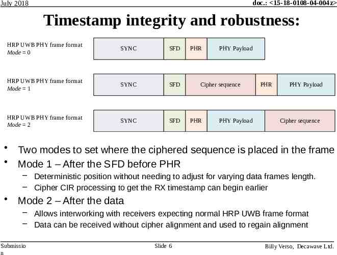
doc.: 15-18-0108-04-004z July 2018 Timestamp integrity and robustness: HRP UWB PHY frame format Mode 0 SYNC SFD HRP UWB PHY frame format Mode 1 SYNC SFD HRP UWB PHY frame format Mode 2 SYNC SFD PHR PHY Payload Cipher sequence PHR PHY Payload PHR PHY Payload Cipher sequence Two modes to set where the ciphered sequence is placed in the frame Mode 1 – After the SFD before PHR – Deterministic position without needing to adjust for varying data frames length. – Cipher CIR processing to get the RX timestamp can begin earlier Mode 2 – After the data – Allows interworking with receivers expecting normal HRP UWB frame format – Data can be received without cipher alignment and used to regain alignment Submissio n Slide 6 Billy Verso, Decawave Ltd.
doc.: 15-18-0108-04-004z July 2018 Ciphered sequence structure: With the ciphered sequence generated cryptographically it will only be correctly received (correctly correlated in the receiver) when both TX and RX parties know the keys and cryptographic scheme The receiver can validate the sequence by measuring the strength of the correlation across the whole sequence To promote interworking between vendors the cryptographic scheme should be defined in the amendment – The proposed scheme is based on AES-128 in counter mode – This has a 128-bit key and a 128-bit nonce – The resultant sequence of 1’s and 0’s define the pulse polarity for the ciphered sequence Submissio n Slide 7 Billy Verso, Decawave Ltd.
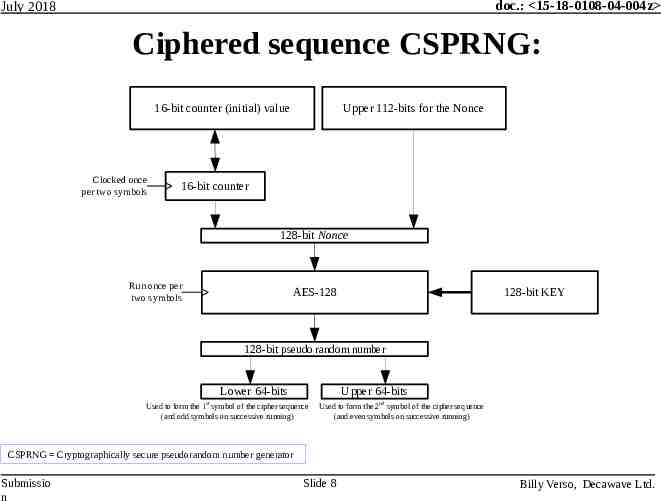
doc.: 15-18-0108-04-004z July 2018 Ciphered sequence CSPRNG: 16-bit counter (initial) value Clocked once per two symbols Upper 112-bits for the Nonce 16-bit counter 128-bit Nonce Run once per two symbols AES-128 128-bit KEY 128-bit pseudo random number Lower 64-bits Upper 64-bits Used to form the 1st symbol of the cipher sequence (and odd symbols on successive running) Used to form the 2nd symbol of the cipher sequence (and even symbols on successive running) CSPRNG Cryptographically secure pseudorandom number generator Submissio n Slide 8 Billy Verso, Decawave Ltd.
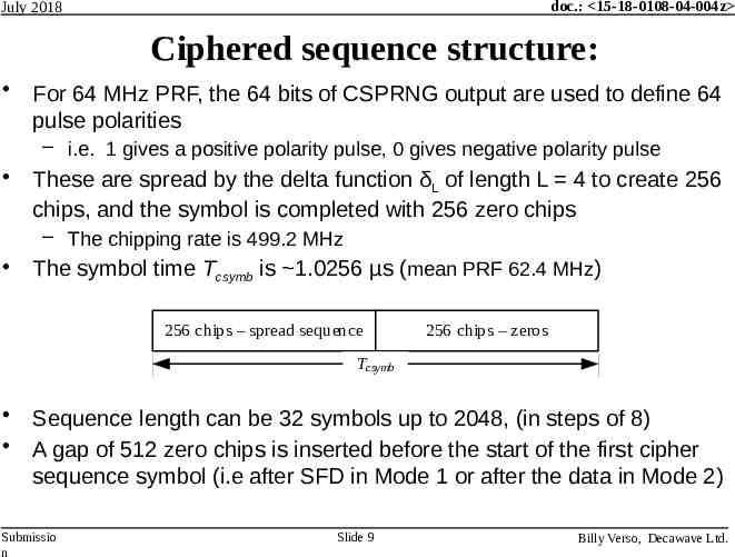
doc.: 15-18-0108-04-004z July 2018 Ciphered sequence structure: For 64 MHz PRF, the 64 bits of CSPRNG output are used to define 64 pulse polarities – i.e. 1 gives a positive polarity pulse, 0 gives negative polarity pulse These are spread by the delta function δL of length L 4 to create 256 chips, and the symbol is completed with 256 zero chips – The chipping rate is 499.2 MHz The symbol time Tcsymb is 1.0256 µs (mean PRF 62.4 MHz) 256 chips – spread sequence 256 chips – zeros Tcsymb Sequence length can be 32 symbols up to 2048, (in steps of 8) A gap of 512 zero chips is inserted before the start of the first cipher sequence symbol (i.e after SFD in Mode 1 or after the data in Mode 2) Submissio n Slide 9 Billy Verso, Decawave Ltd.
doc.: 15-18-0108-04-004z July 2018 Ciphered sequence accumulation side lobes The 256 zero chips forming the 2nd half of each symbol reduce intersymbol interference and also simplify the implementation of digital sidelobe minimization (DSM) algorithms – These DSM algorithms can reduce sidelobes by 25 to 35 dB resulting in lower noise channel impulse response estimates (CIR), generated by accumulation of crosscorrelated symbols The CIR that can be achieved with the ciphered sequence and the DSM algorithm is superior to the CIR obtained from the periodic preamble sequence – With periodic sequences, certain distortions may add coherently in a repeated way, creating specific artefacts in the resultant CIR – With non-periodic sequences, such distortions average out, reducing the overall noise levels in the resultant CIR More details about DSM shall be provided in separate submission Submissio n Slide 10 Billy Verso, Decawave Ltd.
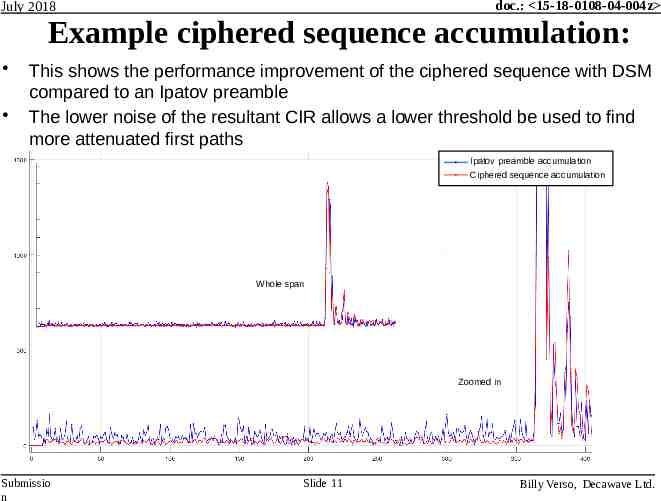
doc.: 15-18-0108-04-004z July 2018 Example ciphered sequence accumulation: This shows the performance improvement of the ciphered sequence with DSM compared to an Ipatov preamble The lower noise of the resultant CIR allows a lower threshold be used to find more attenuated first paths Ipatov preamble accumulation Ciphered sequence accumulation Whole span Zoomed in Submissio n Slide 11 Billy Verso, Decawave Ltd.
doc.: 15-18-0108-04-004z July 2018 Reduced on-air transmission times: Frame duration is a critical parameter: Shorter frames reduce energy consumption – Energy consumption is proportional to frame length Shorter frames give a smaller time window for any attack Shorter frames cause less interference to others Shorter frames experience less interference from others Shorter frames give an increased channel capacity Submissio n Slide 12 Billy Verso, Decawave Ltd.
doc.: 15-18-0108-04-004z July 2018 Frame compression techniques: Send the PHR at the data rate for 6.81 Mb/s and 27 Mb/s frames – Two-way ranging applications typically use fixed data rate and frame formats Compress the preamble and SFD transmission phases – Choose shorter length Ipatov codes to make shorter symbols – Reduce the spreading factor in the preamble sequences The high peak PRF of the HRP UWB PHY affords this possibility – Use Ipatov codes with greater proportion of non-zero elements Increases symbol energy to compensate for shorter symbols Compress the ciphered sequence – Remove the 256 zeros that form the 2nd half of each symbol Compress the PHR and data symbols for new 27 Mb/s data rate – remove the burst time hopping and reduce the guard period duration – Use just BPSK to encode the data, (i.e. no BPM) – Use 8 pulses per burst instead of 2 Increases the symbol energy to get more range Submissio n Slide 13 Billy Verso, Decawave Ltd.
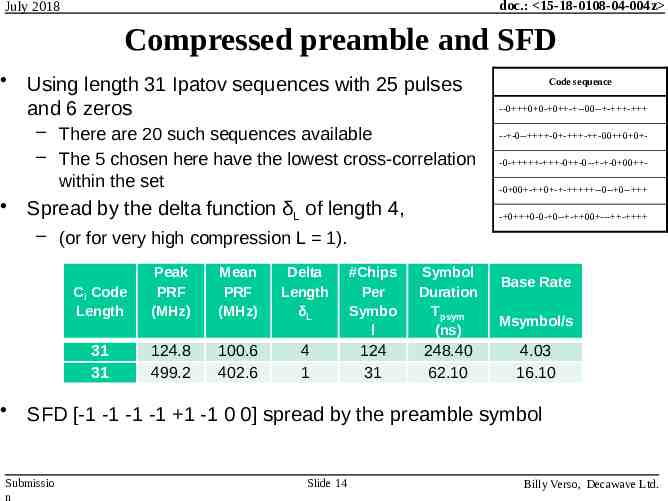
doc.: 15-18-0108-04-004z July 2018 Compressed preamble and SFD Using length 31 Ipatov sequences with 25 pulses and 6 zeros – There are 20 such sequences available – The 5 chosen here have the lowest cross-correlation within the set Spread by the delta function δL of length 4, Code sequence --0 0 0- 0 - --00-- - - -- -0-- -0 - - -00 0 0 -0- - -0 -0-- - -0 00 -0 00 - 0 - - --0-- 0-- - 0 0-0- 0-- - 00 --- - – (or for very high compression L 1). Ci Code Length Peak PRF (MHz) Mean PRF (MHz) Delta Length δL #Chips Per Symbo l Symbol Duration Tpsym (ns) 31 31 124.8 499.2 100.6 402.6 4 1 124 31 248.40 62.10 Base Rate Msymbol/s 4.03 16.10 SFD [-1 -1 -1 -1 1 -1 0 0] spread by the preamble symbol Submissio n Slide 14 Billy Verso, Decawave Ltd.
doc.: 15-18-0108-04-004z July 2018 250 ns preamble symbol vs. 1µs The length 31 preamble symbol allows for faster detection and carrier acquisition; instead of 40μs, it can be done in 18μs Preamble detection works on a symbol by symbol basis using symbol cross correlation, so shorter symbols allow for faster detection Carrier acquisition also works on a symbol basis so the carrier loop is updated more frequently and locks more quickly and robustly with a shorter symbol The SFD duration reduces from 8μs to 2μs saving power Shorter preambles generally have higher cross-correlation peaks, but they are less likely to collide, so they have better overall cross correlation properties All this results in a lower energy solution with less airtime and more channel capacity Submissio n Slide 15 Billy Verso, Decawave Ltd.
doc.: 15-18-0108-04-004z July 2018 Compressed cipher sequence The duration of cipher sequence symbols is halved This is done by removing the zero chips forming the 2nd half of the symbol – The symbol time Tcsymb is then 0.5128 µs and the PRF 124.9 MHz The only gaps inserted are 256 zero chips before and after the full sequence which is otherwise continuous – As before its length can be 32 to 2048 symbols in steps of 8 Optionally a very highly compressed mode can be supported where the delta function length L 1 – Tcsymb is then 0.1282 µs consisting of just 64 chips at the peak PRF of 499.2 MHz per symbol Submissio n Slide 16 Billy Verso, Decawave Ltd.
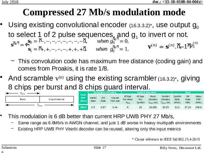
doc.: 15-18-0108-04-004z July 2018 Compressed 27 Mb/s modulation mode Using existing convolutional encoder (16.3.3.2)*, use output g0 to select 1 of 2 pulse sequences,ሺ𝑛ሻand g1 to invert or not. 𝐬0 ሾ , , , , , , , ሿ, 𝐬ሺ𝑛ሻ ቊ 𝐬1 ሾ , , , , , , , ሿ, 𝑤ℎ𝑒𝑛 𝑔0 0, (𝑛) 𝐯 ሺሻ 𝑤ℎ𝑒𝑛 𝑔0𝑛 1, 𝐬 . ሺ 1 (𝑛) ሻ𝑔1 (𝑛) – This convolution code has maximum free distance (coding gain) and comes from Proakis, it is rate 1/8. And scramble v(n) using the existing scrambler (16.3.2)*, giving 8 chips per burst and 8 chips guard interval. Tburst Burst Guard Interval Tdsym Modulation & Coding Peak PRF (MHz) Viterbi Rate RS Rate 499.2 0.5 0.87 Symbol Structure Data Overall FEC rate #Chips Per Burst Ncpb #Chips Per Symbol Burst Duration Tburst (ns) Symbol Duration Tdsym (ns) Symbol Rate (MHz) Bit Rate Mb/s Mean PRF (MHz) 0.44 8 16 16.026 32.05 31.2 27.24 249.6 This modulation is 6 dB better than current HRP UWB PHY 27 Mb/s, – – Same range as 6.8Mb/s in AWGN channel, and just 1 dB worse in heavy multipath environments Existing HRP UWB PHY Viterbi decoder can be reused, altering only the input metrics * Clause reference to IEEE Std 802.15.4-2015 Submissio n Slide 17 Billy Verso, Decawave Ltd.
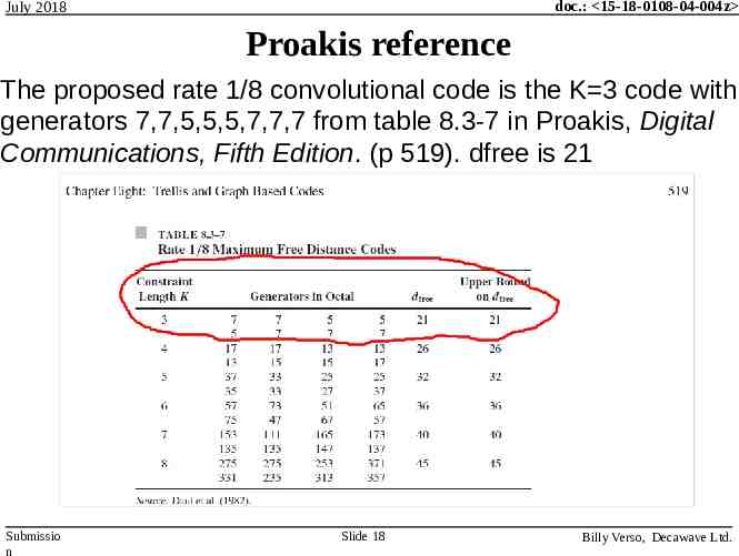
doc.: 15-18-0108-04-004z July 2018 Proakis reference The proposed rate 1/8 convolutional code is the K 3 code with generators 7,7,5,5,5,7,7,7 from table 8.3-7 in Proakis, Digital Communications, Fifth Edition. (p 519). dfree is 21 Submissio n Slide 18 Billy Verso, Decawave Ltd.
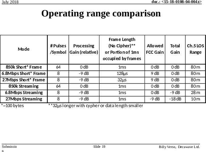
doc.: 15-18-0108-04-004z July 2018 Operating range comparison Mode # Pulses Processing /Symbol Gain (relative) Frame Length (No Cipher)** or Portion of 1ms occupied by frames 850k Short* Frame 64 0 dB 1ms 6.8Mbps Short* Frame 8 -9 dB 128μs 27Mbps Short* Frame 8 -9 dB 32μs 850k Streaming 64 0 dB 1ms 6.8Mbps Streaming 8 -9 dB 1ms 27Mbps Streaming 8 -9 dB 1ms * 100 bytes **32μs longer with cypher or data length smaller Submissio n Slide 19 Allowed FCC Gain Total Gain Ch.5 LOS Range 0 dB 9 dB 9 dB 0 dB 0 dB -9 dB 0 dB 0 dB 0 dB 0 dB -9 dB -18 dB 80 m 80 m 80 m 80 m 28 m 10 m Billy Verso, Decawave Ltd.
doc.: 15-18-0108-04-004z July 2018 Pulse Repetition Frequency (PRF) There has been some discussion in previous sessions about the PRFs proposed in this submission – In particular is a request to not to make large changes in mean PRF between the various elements of the PHY frame because of the effect this has in the adaption of AGC and ADC thresholds However, changing PRF should not be a problem if the pulse amplitude is kept constant because AGC and ADC thresholds need to be frozen early in frame – e.g. soon after preamble is detected This freezing is required both for security and performance reasons Submissio n Slide 20 Billy Verso, Decawave Ltd.
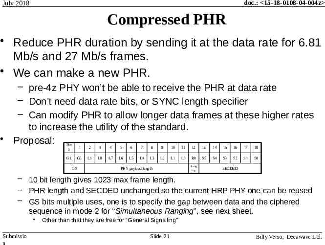
doc.: 15-18-0108-04-004z July 2018 Compressed PHR Reduce PHR duration by sending it at the data rate for 6.81 Mb/s and 27 Mb/s frames. We can make a new PHR. – pre-4z PHY won’t be able to receive the PHR at data rate – Don’t need data rate bits, or SYNC length specifier – Can modify PHR to allow longer data frames at these higher rates to increase the utility of the standard. Proposal: Bit 0 G1 GS 1 2 3 4 5 6 7 8 9 10 11 12 13 14 15 16 17 18 G0 L9 L8 L7 L6 L5 L4 L3 L2 L1 L0 R0 S5 S4 S3 S2 S1 S0 PHY payload length Rang ing SECDED – 10 bit length gives 1023 max frame length. – PHR length and SECDED unchanged so the current HRP PHY one can be reused – GS bits multiple uses, one is to specify the gap between data and the ciphered sequence in mode 2 for “Simultaneous Ranging”, see next sheet. Submissio n Other than that they are free for “General Signalling” Slide 21 Billy Verso, Decawave Ltd.
doc.: 15-18-0108-04-004z July 2018 Simultaneous ranging In certain applications, it is required to measure the distance to the nearest of a number of devices. – e.g. for automotive passive entry with “anchor” points at each corner of a car to determine how far is the key-fob from the car Simultaneous ranging is a method to reduce airtime and battery consumption by configuring the responding devices to respond at almost the same time with overlapping frames Savings for the key fob can be very significant since it can send a poll and treat all 4 responses as a single RX frame – See separate submission on Simultaneous Ranging for more details and various ranging schemes based on it – The next sheet shows the concept for 4 responding devices where each has a different delay between data and the cipher sequence Submissio n Slide 22 Billy Verso, Decawave Ltd.
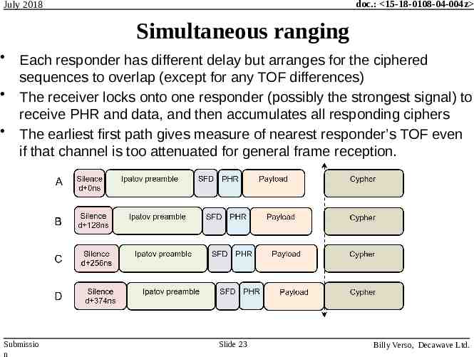
doc.: 15-18-0108-04-004z July 2018 Simultaneous ranging Each responder has different delay but arranges for the ciphered sequences to overlap (except for any TOF differences) The receiver locks onto one responder (possibly the strongest signal) to receive PHR and data, and then accumulates all responding ciphers The earliest first path gives measure of nearest responder’s TOF even if that channel is too attenuated for general frame reception. Submissio n Slide 23 Billy Verso, Decawave Ltd.
doc.: 15-18-0108-04-004z July 2018 Simultaneous ranging The GS bits in the PHR serve to let the receiving PHY know which of the four responders it has locked onto and thereby determine the delay to the cipher sequence To achieve this we need: – A programmable response time (set differently in each responder) – A programmable gap in the transmitter between data and ciphered sequence (set differently in each responder) – A programmable table in the receiver of 4 gaps, GsRxTab[4] (one for each GS encoding 0 to 3) When not being used for Gap Selection the GS bits can be used as “General Signals” of other application specific info – In Mode 2 by setting all GsRxTab entries to same delay (e.g. zero) – Always in Mode 1 where there is a fixed SFD to Cipher gap Submissio n Slide 24 Billy Verso, Decawave Ltd.
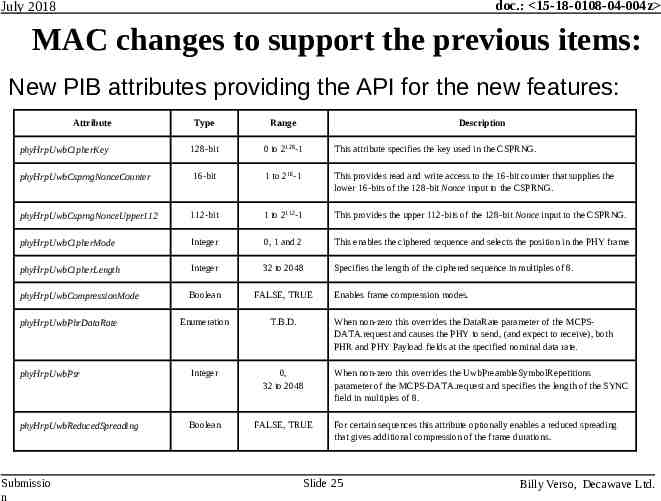
doc.: 15-18-0108-04-004z July 2018 MAC changes to support the previous items: New PIB attributes providing the API for the new features: Attribute Type Range phyHrpUwbCipherKey 128-bit 0 to 2128-1 This attribute specifies the key used in the CSPRNG. phyHrpUwbCsprngNonceCounter 16-bit 1 to 216-1 This provides read and write access to the 16-bit counter that supplies the lower 16-bits of the 128-bit Nonce input to the CSPRNG. phyHrpUwbCsprngNonceUpper112 112-bit 1 to 2112-1 This provides the upper 112-bits of the 128-bit Nonce input to the CSPRNG. phyHrpUwbCipherMode Integer 0, 1 and 2 This enables the ciphered sequence and selects the position in the PHY frame phyHrpUwbCipherLength Integer 32 to 2048 Specifies the length of the ciphered sequence in multiples of 8. phyHrpUwbCompressionMode Boolean FALSE, TRUE Enumeration T.B.D. phyHrpUwbPsr Integer 0, 32 to 2048 phyHrpUwbReducedSpreading Boolean FALSE, TRUE phyHrpUwbPhrDataRate Submissio n Description Enables frame compression modes. When non-zero this overrides the DataRate parameter of the MCPSDATA.request and causes the PHY to send, (and expect to receive), both PHR and PHY Payload fields at the specified nominal data rate. When non-zero this overrides the UwbPreambleSymbolRepetitions parameter of the MCPS-DATA.request and specifies the length of the SYNC field in multiples of 8. For certain sequences this attribute optionally enables a reduced spreading that gives additional compression of the frame durations. Slide 25 Billy Verso, Decawave Ltd.
doc.: 15-18-0108-04-004z July 2018 MAC enhancements for TOF measurement: The current MAC provides ranging counters in the MCPSDATA primitives – This does not promote standardised TOF interworking – It leaves the messaging for TOF measurement to the upper layers – In general it is necessary to communicate response times or roundtrip delay times between the parties to complete the TOF calculation The addition of Information Elements (IEs) by amendment 4e provides a mechanism to standardise ranging messages This also provides an opportunity improve the utility of the MAC such that it would be possible for a TOF estimate to be completed with just two messages, one TX and one RX – See next sheet Submissio n Slide 26 Billy Verso, Decawave Ltd.
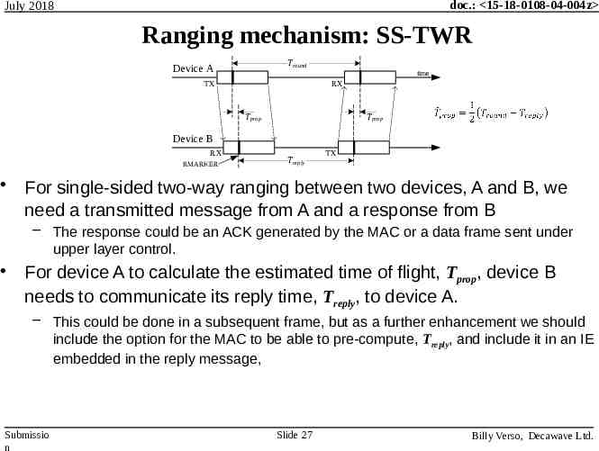
doc.: 15-18-0108-04-004z July 2018 Ranging mechanism: SS-TWR Tround Device A time TX RX Tprop Tprop Device B RX RMARKER Treply TX For single-sided two-way ranging between two devices, A and B, we need a transmitted message from A and a response from B – The response could be an ACK generated by the MAC or a data frame sent under upper layer control. For device A to calculate the estimated time of flight, Tprop, device B needs to communicate its reply time, Treply, to device A. – This could be done in a subsequent frame, but as a further enhancement we should include the option for the MAC to be able to pre-compute, Treply, and include it in an IE embedded in the reply message, Submissio n Slide 27 Billy Verso, Decawave Ltd.
doc.: 15-18-0108-04-004z July 2018 Specifying the IEs for TOF measurement: This may seem like a lot of work, but it is not, since a model for this already exists . All the necessary IE and mechanisms (and the text) for what is needed have already been developed and included in the recently published IEEE 802.15.8-2017 standard The proposal here is to copy the relevant text relating to ranging and IE’s from the original TG submission doc: – 15-15-0429-01-0008-text-for-relative-positioning-and-location.docx The only change needed is re-numbering the IEs – The 802.15.8 IEs for ranging will need to be merged into the 802.15.4 IE table which should be a small task Submissio n Slide 28 Billy Verso, Decawave Ltd.
doc.: 15-18-0108-04-004z July 2018 THE END Submissio n Slide 29 Billy Verso, Decawave Ltd.