CMPE 412 Software Engineering Asst.Prof.Dr.Duygu Çelik Ertuğrul


47 Slides583.73 KB
CMPE 412 Software Engineering Asst.Prof.Dr.Duygu Çelik Ertuğrul Room: CMPE 206 Email: [email protected] 1
Software Development Life Cycle (SDLC) “You’ve got to be very careful if you don’t know where you’re going, because you might not get there.” Yogi Berra 2
SDLC Model A framework that describes the activities performed at each stage of a software development project. 3
4
Waterfall Model Requirements – defines needed information, function, behavior, performance and interfaces. Design – data structures, software architecture, interface representations, algorithmic details. Implementation – source code, database, user documentation, testing. It is plan-driven https://www.youtube.com/watch?v 5A5XCuWMG4o 5
Waterfall Strengths Easy to understand, easy to use Provides structure to inexperienced staff Milestones are well understood Sets requirements stability Good for management control (plan, staff, track) Works well when quality is more important than cost or schedule 6
Waterfall Deficiencies All requirements must be known at beginning Can give a false impression of progress Does not reflect problem-solving of software development – iterations of phases Integration is one big bang at the end Little opportunity for customer to preview the system (until it may be too late) 7
When to use the Waterfall Model Requirements are very well known Product definition is stable Technology is understood New version of an existing product Carrying an existing product to a new platform (i.e. diff language). 8
V-Shaped SDLC Model It is plan-driven A modified of the Waterfall model that highlights the verification and validation of the product. Testing of the product is planned in parallel with a corresponding phase of development 9
V-Shaped Steps Project and Requirements Planning – allocate resources Product Requirements and Specification Analysis – complete specification of the software system Architecture or High-Level Design – defines how software functions fulfill the design Detailed Design – develop algorithms for each architectural component Production, operation and maintenance – provide for enhancement and corrections System and acceptance testing – check the entire software system in its environment (client environment) Integration and Testing – check that modules interconnect correctly Unit testing – check that each module acts as expected Coding – transform algorithms into software 10
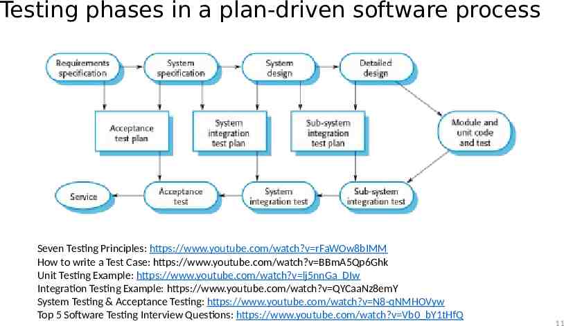
Testing phases in a plan-driven software process Seven Testing Principles: https://www.youtube.com/watch?v rFaWOw8bIMM How to write a Test Case: https://www.youtube.com/watch?v BBmA5Qp6Ghk Unit Testing Example: https://www.youtube.com/watch?v lj5nnGa DIw Integration Testing Example: https://www.youtube.com/watch?v QYCaaNz8emY System Testing & Acceptance Testing: https://www.youtube.com/watch?v N8-qNMHOVyw Top 5 Software Testing Interview Questions: https://www.youtube.com/watch?v Vb0 bY1tHfQ 11
V-Shaped Strengths Stress planning for verification and validation of the product in early stages of product development Why testing is important? Each deliverable must be testable Project management can track progress by milestones Easy to use 12
V-Shaped Weaknesses Does not easily handle concurrent events/tasks, because tasks are created plan-driven Does not handle iterations or phases Does not easily handle dynamic changes in requirements (diffucult to change plans in any time!!!) Does not contain risk analysis activities 13
When to use the V-Shaped Model Excellent choice for systems requiring high reliability – e.g. hospital patient control applications All requirements are known clearly If solution and technology are known well 14
Structured Evolutionary Prototyping Model Developers build a prototype during the requirements phase Prototype is evaluated by end users Users give corrective feedback Developers improve the prototype When the user is satisfied, the prototype code is brought up to the standards needed for a final product. (End of Project!!!) 15
Structured Evolutionary Prototyping Steps A preliminary project plan is developed A partial high-level paper model is created The model is source for a partial requirements specification A prototype is built with basic and critical attributes The designer builds the database user interface algorithmic functions The designer demonstrates the prototype, the user evaluates for problems and suggests improvements. This loop continues until the user is satisfied https://www.youtube.com/watch?v bAEnaGG8Otc 16
Structured Evolutionary Prototyping Strengths Customers can “see” the system requirements as they are being gathered Developers learn from customers A more accurate end product Unexpected requirements accommodated/considered Allows for flexible design and development Steady, visible signs of progress produced Interaction with the prototype provides to awareness of additional needed functionality 17
Structured Evolutionary Prototyping Weaknesses Overall maintainability may be unnoticed. The customer may want the prototype delivered. Process may continue forever (scope creep-sürünerek ilerler), Namely, Process is improving gradually 18
When to use Structured Evolutionary Prototyping If Requirements are unstable or have to be clarified Develop user interfaces Short-life demonstrations New, original development 19
Incremental SDLC Model Construct a partial implementation of a total system Then slowly functionality add increased The incremental model prioritizes requirements of the system and then implements them in groups. Each subsequent release of the system: adds function to the previous release, until all designed functionality has been implemented. https://www.youtube.com/watch?v gcpOZi6Hz38 20
Incremental development https://www.youtube.com/watch?v gcpOZi6Hz38 http://moodle.autolab.uni-pannon.hu/Mecha tananyag/szoftverfejlesztesi folyamatok angol/ch03.html
Incremental Model Strengths You can develop high-risk or major functions first Each release delivers an operational product Customer can respond to each build from each increment Uses “divide and conquer” breakdown of tasks Lowers initial delivery cost Initial product delivery is faster Customers get important functionality early Risk of changing requirements is reduced 22
Incremental Model Weaknesses Requires good planning and design Requires early definition of a complete and fully functional system to allow for the definition of increments Well-defined module interfaces are required (some will be developed long before others) Total cost of the complete system is not lower 23
When to use the Incremental Model Most of the requirements are known up-front but are expected to evolve over time A need to get basic functionality to the market early On projects which have long development schedules On a project with new technology 24
Spiral SDLC Model Adds risk analysis and RAD prototyping to the waterfall model Each cycle involves the same sequence of steps as the waterfall process model https://www.youtube.com/watch?v mp22SDTnsQQ 25
Spiral Quadrant Determine objectives, alternatives and constraints Objectives: functionality, performance, hardware/software interface, critical success factors, etc. Alternatives: build, reuse, buy, sub-contract, etc. Constraints: cost, schedule, interface, etc. 26
Spiral Quadrant Evaluate alternatives, identify and resolve risks Study alternatives relative to objectives and constraints Identify risks (lack of experience, new technology, tight schedules, poor process, etc. Resolve (Analyze) risks (evaluate if money could be lost by continuing system development 27
Spiral Quadrant Develop next-level product Typical activites: Create a design Review design Develop code Examine code Test product 28
Spiral Quadrant Plan next phase Typical activities Review the project Develop the next phase plan 29
Spiral Model Strengths Provides early indication of possible risks, without much cost Users see the system early because of rapid prototyping tools high-risk or critical functions of customer are developed first The design does not have to be perfect Users can be closely tied to all lifecycle steps Early and frequent feedback from users (in each cycle prototyping) Cumulative costs assessed frequently 30
Spiral Model Weaknesses Time spent for evaluating risks too large for small or low-risk projects Time spent planning, resetting objectives, doing risk analysis and prototyping may be may be unnecessary The model is complex Risk assessment expertise is required Spiral may continue indefinitely Developers must be reassigned/moved during non-development phase activities (idle time) May be hard to define objective, demonstrable milestones that indicate possibility to proceed to the next iteration 31
When to use Spiral Model When creation of a prototype is necessary for any SW prj When costs and risk evaluation is important (e.g., patient service program ) For medium to high-risk projects When Users are unsure of their needs Requirements are complex When new product sector (requirments are unknown yet) Significant and various changes are expected (research and exploration) 32
The Rational Unified Process https://www.youtube.com/watch?v YgkhFH8g0J4 RUP brings together aspects of the 3 generic process models (‘waterfall’ model, incremental development, and reuse-oriented development). RUP involves 3 perspectives: A dynamic perspective that shows phases over time: Inception (scope,estimations), Elaboration (design architecture), Construction (implementation), Transtion (all tasks after implementation to production) A static perspective that shows process activities Businnes Modelling, Requirements, Analysis&Design, Implementation, Test, Deployment A practice perspective that suggests good practice. 33
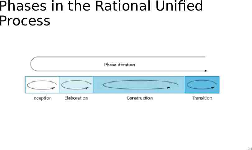
Phases in the Rational Unified Process 34
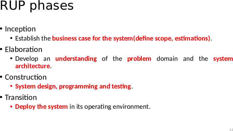
RUP phases Inception Establish the business case for the system(define scope, estimations). Elaboration Develop an understanding of the problem domain and the system architecture. Construction System design, programming and testing. Transition Deploy the system in its operating environment. 35
RUP iteration There are two iteration types in RUP: In-phase iteration Each phase is iterative with results developed incrementally. Cross-phase iteration As shown by the loop in the RUP model, the whole set of phases may be passed incrementally. 36
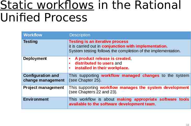
Static workflows in the Rational Unified Process Workflow Description Business modelling The business processes business use cases. Requirements Actors who interact with the system are identified and use cases are developed to model the system requirements. Analysis and design A design model is created and documented using architectural models, component models, object models and sequence models. Implementation The components in the system are implemented and structured into implementation sub-systems. Automatic code generation from design models helps accelerate this process. are modelled using 37
Static workflows in the Rational Unified Process Workflow Description Testing Testing is an iterative process it is carried out in conjunction with implementation. System testing follows the completion of the implementation. Deployment Configuration and change management This supporting workflow managed changes to the system (see Chapter 25). Project management This supporting workflow manages the system development (see Chapters 22 and 23). Environment This workflow is about making appropriate software tools available to the software development team. A product release is created, distributed to users and installed in their workplace. 38
Agile SDLC’s Speed up or bypass one or more life cycle phases Usually less formal and reduced scope Used for time-critical applications Used in organizations that employ disciplined methods 39
Some Agile Methods Adaptive Software Development (ASD) Feature Driven Development (FDD) Crystal Clear Dynamic Software Development Method (DSDM) Rapid Application Development (RAD) Extreme Programming (XP) 40
Rapid Application Development Model (RAD) https://www.youtube.com/watch?v Iuuj-GgJtXU&spfreload 10 Requirements planning phase (a workshop applying structured discussion of business problems) User description phase – automated tools used to collect information from users Construction phase – productivity tools, such as code generators, screen generators, etc. inside a time-box. (“Do until done”) Cutover phase -- installation of the system, user acceptance testing and user training https://www.youtube.com/watch?v gPgsKLtwJ68&spfreload 10 https://www.youtube.com/watch?v X6QzyHiSPf0 https://www.youtube.com/watch?v BoQzy N7U2w 41
RAD Strengths Reduced cycle time and improved productivity with fewer people means lower costs Time-box approach will be useful for cost and schedule risk of project Customer involved throughout the complete cycle minimizes risk of not achieving customer satisfaction and business needs Focus moves from documentation to code . Uses modeling concepts to capture information about business, data, and processes. 42
RAD Weaknesses Accelerated development process must give quick responses to the user Hard to use with legacy (older) systems Requires a system that can be modularized Developers and customers must be dedicated to rapid-fire activities in an shortened time frame. 43
When to use RAD If you know reasonably well-known requirements of new system If it is possible User involved throughout the life cycle If the project can be time-boxed If the functionality of project is delivered in increments High performance not required Low technical risks System can be modularized 44
Extreme Programming - XP When it is considered? For small-to-medium-sized teams developing software with unclear or rapidly changing requirements Coding is the key activity throughout a software project Communication among team-mates is done with code Life cycle and behavior of complex objects defined in test cases – again in code 45
XP Practices (1-6) 1. Planning game – determine scope of the next release by combining business priorities and technical estimates 2. Small releases – put a simple system into production, then release new versions in very short cycle 3. Metaphor – all development is guided by a simple shared story of how the whole system works 4. Simple design – system is designed as simply as possible (extra complexity removed as soon as found) 5. Testing – programmers continuously write unit tests; but customers write tests for features 6. Refactoring – programmers continuously restructure the system without changing its behavior to remove duplication and simplify 46
XP Practices (7 – 12) 7. Pair-programming -- all production code is written with two programmers at one machine 8. Collective ownership – anyone can change any code anywhere in the system at any time. 9. Continuous integration – integrate and build the system many times a day – every time a task is completed. 10. 40-hour week – work no more than 40 hours a week as a rule 11. On-site customer – a user is on the team and available full-time to answer questions 12. Coding standards – programmers write all code in accordance with rules emphasizing communication through the code 47