Chapter 4: Network Access Instructor Materials CCNA Routing


70 Slides9.12 MB
Chapter 4: Network Access Instructor Materials CCNA Routing and Switching Introduction to Networks v6.0
Chapter 4: Network Access Introduction to Networks 6.0 Planning Guide 2016 Cisco and/or its affiliates. All rights reserved. Cisco Confidential 3
Chapter 4: Network Access CCNA Routing and Switching Introduction to Networks v6.0
Chapter 4 - Sections & Objectives 4.1 Physical Layer Protocols Explain how physical layer protocols and services support communications across data networks. Identify device connectivity options. Describe the purpose and functions of the physical layer in the network. Describe basic principles of the physical layer standards. 4.2 Network Media Build a simple network using the appropriate media. Identify the basic characteristics of copper cabling. Build a UTP cable used in Ethernet networks. (scope - does not include cabling area discussion) Describe fiber optic cabling and its main advantages over other media. Connect devices using wired and wireless media. 2016 Cisco and/or its affiliates. All rights reserved. Cisco Confidential 13
Chapter 4 - Sections & Objectives (Cont.) 4.3 Data Link Layer Protocols Explain the role of the data link layer in supporting communications across data networks. Describe the purpose and function of the data link layer in preparing communication for transmission on specific media. 4.4 Media Access Control Compare media access control techniques and logical topologies used in networks. Compare the functions of logical topologies and physical topologies. Describe the basic characteristics of media access control methods on WAN topologies. Describe the basic characteristics of media access control methods on LAN topologies. Describe the characteristics and functions of the data link frame. 2016 Cisco and/or its affiliates. All rights reserved. Cisco Confidential 14
4.1 Physical Layer Protocols 2016 Cisco and/or its affiliates. All rights reserved. Cisco Confidential 15
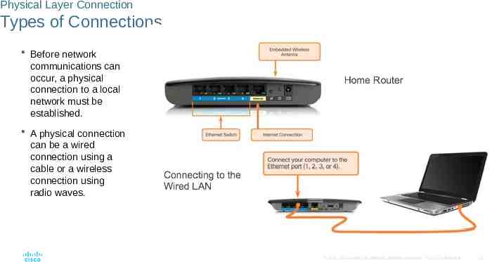
Physical Layer Connection Types of Connections Before network communications can occur, a physical connection to a local network must be established. A physical connection can be a wired connection using a cable or a wireless connection using radio waves. 2016 Cisco and/or its affiliates. All rights reserved. Cisco Confidential 16
Physical Layer Connection Network Interface Cards Network Interface Cards (NICs) connect a device to a network. Used for a wired connection. Wireless Local Area Network (WLAN) NICs are used for wireless connections. 2016 Cisco and/or its affiliates. All rights reserved. Cisco Confidential 17
Purpose of the Physical Layer The Physical Layer Provides the means to transport the bits that make up a data link layer frame across the network media. Accepts a complete frame from the data link layer and encodes it as a series of signals that are transmitted onto the local media. Encoded bits that comprise a frame are received by either an end device or an intermediate device. 2016 Cisco and/or its affiliates. All rights reserved. Cisco Confidential 18
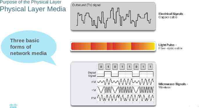
Purpose of the Physical Layer Physical Layer Media Three basic forms of network media 2016 Cisco and/or its affiliates. All rights reserved. Cisco Confidential 19
Purpose of the Physical Layer Physical Layer Standards International Organization for Standardization (ISO) Telecommunications Industry Association/Electronic Industries Association (TIA/EIA) International Telecommunication Union (ITU) American National Standards Institute (ANSI) Institute of Electrical and Electronics Engineers (IEEE) 2016 Cisco and/or its affiliates. All rights reserved. Cisco Confidential 20
Purpose of the Physical Layer Lab - Identifying Network Devices and Cabling 2016 Cisco and/or its affiliates. All rights reserved. Cisco Confidential 21
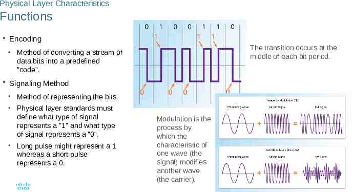
Physical Layer Characteristics Functions Encoding The transition occurs at the middle of each bit period. Method of converting a stream of data bits into a predefined "code”. Signaling Method Method of representing the bits. Physical layer standards must define what type of signal represents a "1" and what type of signal represents a "0”. Long pulse might represent a 1 whereas a short pulse represents a 0. Modulation is the process by which the characteristic of one wave (the signal) modifies another wave (the carrier). 2016 Cisco and/or its affiliates. All rights reserved. Cisco Confidential 22
Physical Layer Characteristics Bandwidth Capacity of a medium to carry data. Digital bandwidth measures the amount of data that can flow from one place to another in a given amount of time. Bandwidth is sometimes thought of as the speed that bits travel, however this is not accurate. In both 10Mb/s and 100Mb/s Ethernet, the bits are sent at the speed of electricity. The difference is the number of bits that are transmitted per second. 2016 Cisco and/or its affiliates. All rights reserved. Cisco Confidential 23
Physical Layer Characteristics Throughput Measure of the transfer of bits across the media over a given period of time. Usually does not match the specified bandwidth in physical layer implementations due to many factors. Amount of traffic Type of traffic Latency created by network devices encountered between source and destination Goodput is throughput minus traffic overhead for establishing sessions, acknowledgments, and encapsulation. 2016 Cisco and/or its affiliates. All rights reserved. Cisco Confidential 24
Physical Layer Characteristics Types of Physical Media The figure shows different types of interfaces and ports available on a 1941 router. 2016 Cisco and/or its affiliates. All rights reserved. Cisco Confidential 25
4.2 Network Media 2016 Cisco and/or its affiliates. All rights reserved. Cisco Confidential 26
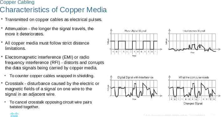
Copper Cabling Characteristics of Copper Media Transmitted on copper cables as electrical pulses. Attenuation - the longer the signal travels, the more it deteriorates. All copper media must follow strict distance limitations. Electromagnetic interference (EMI) or radio frequency interference (RFI) - distorts and corrupts the data signals being carried by copper media. To counter copper cables wrapped in shielding. Crosstalk - disturbance caused by the electric or magnetic fields of a signal on one wire to the signal in an adjacent wire. To cancel crosstalk opposing circuit wire pairs twisted together. 2016 Cisco and/or its affiliates. All rights reserved. Cisco Confidential 27
Copper Cabling Copper Media There are three main types of copper media used in networking. 2016 Cisco and/or its affiliates. All rights reserved. Cisco Confidential 28
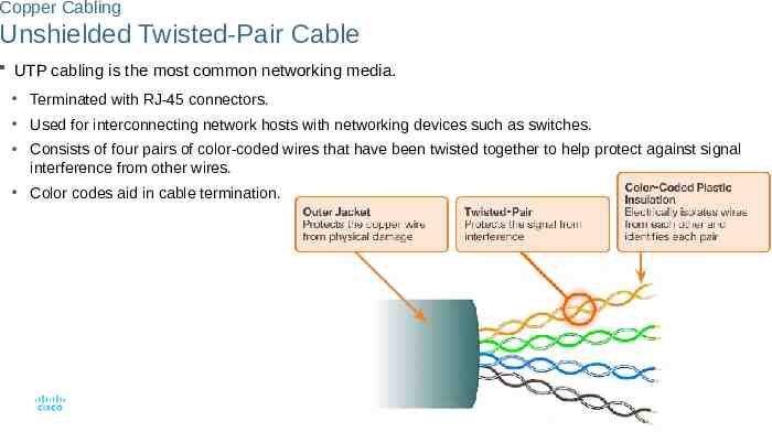
Copper Cabling Unshielded Twisted-Pair Cable UTP cabling is the most common networking media. Terminated with RJ-45 connectors. Used for interconnecting network hosts with networking devices such as switches. Consists of four pairs of color-coded wires that have been twisted together to help protect against signal interference from other wires. Color codes aid in cable termination. 2016 Cisco and/or its affiliates. All rights reserved. Cisco Confidential 29
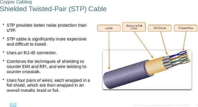
Copper Cabling Shielded Twisted-Pair (STP) Cable STP provides better noise protection than UTP. STP cable is significantly more expensive and difficult to install. Uses an RJ-45 connector. Combines the techniques of shielding to counter EMI and RFI, and wire twisting to counter crosstalk. Uses four pairs of wires, each wrapped in a foil shield, which are then wrapped in an overall metallic braid or foil. 2016 Cisco and/or its affiliates. All rights reserved. Cisco Confidential 30
Copper Cabling Coaxial Cable Coax consists of: A copper conductor used to transmit the electronic signals. A layer of flexible plastic insulation surrounding a copper conductor. The insulating material is surrounded in a woven copper braid, or metallic foil, that acts as the second wire in the circuit and as a shield for the inner conductor. The entire cable is covered with a cable jacket to prevent minor physical damage. UTP cable has essentially replaced coaxial cable in modern Ethernet installations but is used in: Wireless installations: Coaxial cables attach antennas to wireless devices. Cable Internet installations 2016 Cisco and/or its affiliates. All rights reserved. Cisco Confidential 31
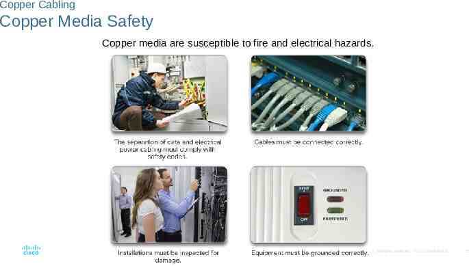
Copper Cabling Copper Media Safety Copper media are susceptible to fire and electrical hazards. 2016 Cisco and/or its affiliates. All rights reserved. Cisco Confidential 32
UTP Cabling Properties of UTP Cabling Consists of four pairs of color-coded copper wires that have been twisted together and then encased in a flexible plastic sheath. Small size can be advantageous during installation. UTP cable does not use shielding to counter the effects of EMI and RFI. Cancellation: When two wires in an electrical circuit are placed close together, their magnetic fields are the exact opposite of each other and cancel out any outside EMI and RFI signals. Notice that the orange/orange white pair is twisted less than the blue/blue white pair. Each colored pair is twisted a different number of times. Varies the number of twists per wire pair to further enhance the cancellation effect of a paired circuit. 2016 Cisco and/or its affiliates. All rights reserved. Cisco Confidential 33
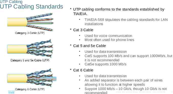
UTP Cabling UTP Cabling Standards UTP cabling conforms to the standards established by TIA/EIA. TIA/EIA-568 stipulates the cabling standards for LAN installations Cat 3 Cable Used for voice communication Most often used for phone lines Cat 5 and 5e Cable Used for data transmission Cat5 supports 100 Mb/s and can support 1000Mb/s, but it is not recommended Cat5e supports 1000 Mb/s Cat 6 Cable Used for data transmission An added separator is between each pair of wires allowing it to function at higher speeds Support 1000 Mb/s – 10 Gb/s, though 10 Gb/s is not 2016 Cisco and/or its affiliates. All rights reserved. Cisco Confidential recommended 34
UTP Cabling UTP Connectors UTP cable terminated with an RJ-45 connector. TIA/EIA-568 standard describes the wire color codes to pin assignments (pinouts) for Ethernet cables. RJ-45 connector is the male component, crimped at the end of the cable. Socket is the female component of a network device, wall, cubicle partition outlet, or patch panel. Essential that all copper media terminations be of high quality to ensure optimum performance with current and future network technologies. 2016 Cisco and/or its affiliates. All rights reserved. Cisco Confidential 35
UTP Cabling Types of UTP Cable 2016 Cisco and/or its affiliates. All rights reserved. Cisco Confidential 36
UTP Cabling Testing UTP Cables UTP Testing Parameters: Wire map Cable length Signal loss due to attenuation Crosstalk 2016 Cisco and/or its affiliates. All rights reserved. Cisco Confidential 37
UTP Cabling Lab - Building an Ethernet Crossover Cable 2016 Cisco and/or its affiliates. All rights reserved. Cisco Confidential 38
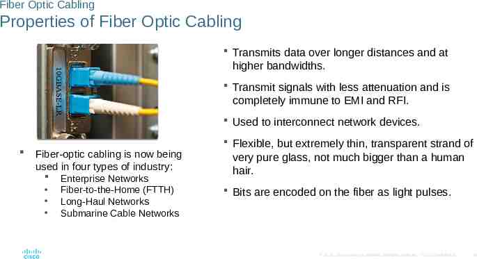
Fiber Optic Cabling Properties of Fiber Optic Cabling Transmits data over longer distances and at higher bandwidths. Transmit signals with less attenuation and is completely immune to EMI and RFI. Used to interconnect network devices. Fiber-optic cabling is now being used in four types of industry: Enterprise Networks Fiber-to-the-Home (FTTH) Long-Haul Networks Submarine Cable Networks Flexible, but extremely thin, transparent strand of very pure glass, not much bigger than a human hair. Bits are encoded on the fiber as light pulses. 2016 Cisco and/or its affiliates. All rights reserved. Cisco Confidential 39
Fiber Optic Cabling Fiber Media Cable Design Jacket Protects the fiber against abrasion, moisture, and other contaminants. Composition can vary depending on the cable usage. Strengthening Material Surrounds the buffer, prevents the fiber cable from being stretched when it is being pulled. Often the same material used to produce bulletproof vests. Buffer Used to help shield the core and cladding from damage. Cladding Tends to act like a mirror by reflecting light back in the core of the fiber. Keeps light in the core as it travels down the fiber. Core Light transmission element at the center of the optical fiber. Core is typically silica or glass. Light pulses travel through the fiber core. 2016 Cisco and/or its affiliates. All rights reserved. Cisco Confidential 40
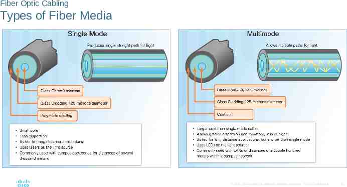
Fiber Optic Cabling Types of Fiber Media 2016 Cisco and/or its affiliates. All rights reserved. Cisco Confidential 41
Fiber Optic Cabling Fiber-Optic Connectors Light can only travel in one direction over optical fiber, two fibers are required to support the full duplex operation. Straight-Tip (ST) Connectors One of the first connector types used. Locks securely with a “twist-on/twist-off”. Subscriber Connector (SC) Connectors Referred to as square or standard connector. Uses a push-pull mechanism to ensure positive insertion. Used with multimode and single-mode fiber. Lucent Connector (LC) Simplex Connectors Smaller version of SC and popular due to size. Duplex Multimode LC Connectors Similar to LC but using a duplex connector. 2016 Cisco and/or its affiliates. All rights reserved. Cisco Confidential 42
Fiber Optic Cabling Fiber-Optic Connectors (Cont.) Fiber patch cords are required for interconnecting infrastructure devices. Yellow jacket is for single-mode fiber cables Orange (or aqua) for multimode fiber cables. Fiber cables should be protected with a small plastic cap when not in use. 2016 Cisco and/or its affiliates. All rights reserved. Cisco Confidential 43
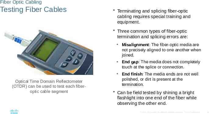
Fiber Optic Cabling Testing Fiber Cables Terminating and splicing fiber-optic cabling requires special training and equipment. Three common types of fiber-optic termination and splicing errors are: Misalignment: The fiber-optic media are not precisely aligned to one another when joined. End gap: The media does not completely touch at the splice or connection. Optical Time Domain Reflectometer (OTDR) can be used to test each fiberoptic cable segment End finish: The media ends are not well polished, or dirt is present at the termination. Can be field tested by shining a bright flashlight into one end of the fiber while observing the other end. 2016 Cisco and/or its affiliates. All rights reserved. Cisco Confidential 44
Fiber Optic Cabling Fiber versus Copper 2016 Cisco and/or its affiliates. All rights reserved. Cisco Confidential 45
Wireless Media Properties of Wireless Media Wireless media carry electromagnetic signals that represent the binary digits of data communications using radio or microwave frequencies. Wireless areas of concern: Coverage area: Construction materials used in buildings and structures, and the local terrain, will limit the coverage. Interference: Disrupted by such common devices as fluorescent lights, microwave ovens, and other wireless communications. Security: Devices and users, not authorized for access to the network, can gain access to the transmission. Shared medium: Only one device can send or receive at a time and the wireless medium is shared amongst all wireless users. 2016 Cisco and/or its affiliates. All rights reserved. Cisco Confidential 46
Wireless Media Types of Wireless Media Wi-Fi: Standard IEEE 802.11 Uses Carrier/Sense Multiple Access/Collision Avoidance (CSMA/CA). Wireless NIC must wait till channel is clear. Bluetooth: Standard IEEE 802.15 Wireless Personal Area Network (WPAN) Uses a device pairing process for distances 1 to 100 meters WiMAX: Standard IEEE 802.16 Worldwide Interoperability for Microwave Access Wireless broadband access. 2016 Cisco and/or its affiliates. All rights reserved. Cisco Confidential 47
Wireless Media Wireless LAN Wireless LAN requires the following network devices: Wireless Access Point (AP): Concentrates the wireless signals from users and connects to the existing copperbased network infrastructure, such as Ethernet. Wireless NIC adapters: Provide wireless communication capability to each network host. Home and small business wireless routers integrate the functions of a router, switch, and access point into one device. 2016 Cisco and/or its affiliates. All rights reserved. Cisco Confidential 48
Wireless Media Packet Tracer - Connecting a Wired and Wireless LAN 2016 Cisco and/or its affiliates. All rights reserved. Cisco Confidential 49
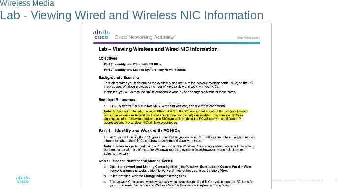
Wireless Media Lab - Viewing Wired and Wireless NIC Information 2016 Cisco and/or its affiliates. All rights reserved. Cisco Confidential 50
4.3 Data Link Protocols 2016 Cisco and/or its affiliates. All rights reserved. Cisco Confidential 51
Purpose of the Data Link Layer The Data Link Layer 2016 Cisco and/or its affiliates. All rights reserved. Cisco Confidential 52
Purpose of the Data Link Layer The Data Link Layer (Cont.) Layer 2 Data Link Addresses 2016 Cisco and/or its affiliates. All rights reserved. Cisco Confidential 53
Purpose of the Data Link Layer Data Link Sublayers Data link layer is divided into two sublayers: Logical Link Control (LLC) Communicates with the network layer. Identifies which network layer protocol is being used for the frame. Allows multiple Layer 3 protocols, such as IPv4 and IPv6, to utilize the same network interface and media. Media Access Control (MAC) Defines the media access processes performed by the hardware. Provides data link layer addressing and access to various network technologies. Communicates with Ethernet to send and receive frames over copper or fiber-optic cable. Communicates with wireless technologies such as Wi-Fi and Bluetooth. 2016 Cisco and/or its affiliates. All rights reserved. Cisco Confidential 54
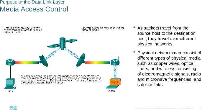
Purpose of the Data Link Layer Media Access Control As packets travel from the source host to the destination host, they travel over different physical networks. Physical networks can consist of different types of physical media such as copper wires, optical fibers, and wireless consisting of electromagnetic signals, radio and microwave frequencies, and satellite links. 2016 Cisco and/or its affiliates. All rights reserved. Cisco Confidential 55
Purpose of the Data Link Layer Providing Access to Media At each hop along the path, a router: Accepts a frame from a medium De-encapsulates the frame Re-encapsulates the packet into a new frame 2016 Cisco and/or its affiliates. All rights reserved. Forwards the new frame appropriate to the medium of that segment Cisco Confidential 56
Purpose of the Data Link Layer Data Link Layer Standards Engineering organizations that define open standards and protocols that apply to the network access layer include: Institute of Electrical and Electronics Engineers (IEEE) International Telecommunication Union (ITU) International Organization for Standardization (ISO) American National Standards Institute (ANSI) 2016 Cisco and/or its affiliates. All rights reserved. Cisco Confidential 57
4.4 Media Access Control 2016 Cisco and/or its affiliates. All rights reserved. Cisco Confidential 58
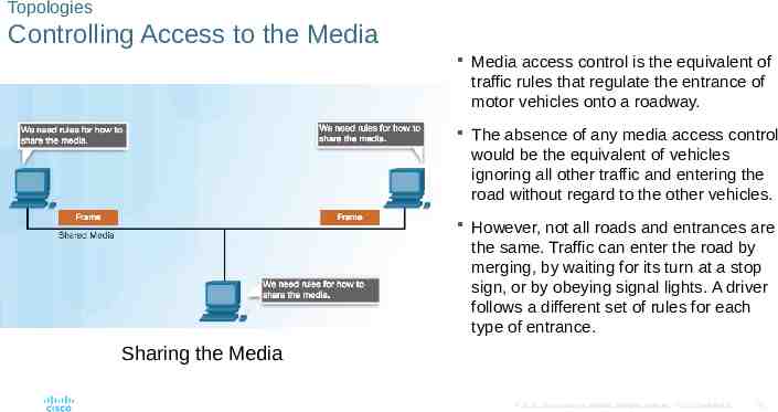
Topologies Controlling Access to the Media Media access control is the equivalent of traffic rules that regulate the entrance of motor vehicles onto a roadway. The absence of any media access control would be the equivalent of vehicles ignoring all other traffic and entering the road without regard to the other vehicles. However, not all roads and entrances are the same. Traffic can enter the road by merging, by waiting for its turn at a stop sign, or by obeying signal lights. A driver follows a different set of rules for each type of entrance. Sharing the Media 2016 Cisco and/or its affiliates. All rights reserved. Cisco Confidential 59
Topologies Physical and Logical Topologies Physical topology - Refers to the physical connections and identifies how end devices and infrastructure devices such as routers, switches, and wireless access points are interconnected. 2016 Cisco and/or its affiliates. All rights reserved. Cisco Confidential 60
Topologies Physical and Logical Topologies (Cont.) Logical Topology: Refers to the way a network transfers frames from one node to the next. These logical signal paths are defined by data link layer protocols. 2016 Cisco and/or its affiliates. All rights reserved. Cisco Confidential 61
WAN Topologies Common Physical WAN Topologies Point-to-Point - Permanent link between two endpoints. Hub and Spoke - A central site interconnects branch sites using point-topoint links. Mesh - Provides high availability, but requires that every end system be interconnected to every other system. Administrative and physical costs can be significant. 2016 Cisco and/or its affiliates. All rights reserved. Cisco Confidential 62
WAN Topologies Physical Point-to-Point Topology Frames are placed on the media by the node at one end and taken from the media by the node at the other end of the point-to-point circuit. 2016 Cisco and/or its affiliates. All rights reserved. Cisco Confidential 63
WAN Topologies Logical Point-to-Point Topology End nodes communicating in a point-to-point network can be physically connected via a number of intermediate devices. However, the use of physical devices in the network does not affect the logical topology. The logical connection between nodes forms what is called a virtual circuit. 2016 Cisco and/or its affiliates. All rights reserved. Cisco Confidential 64
WAN Topologies Logical Point-to-Point Topology (Cont.) 2016 Cisco and/or its affiliates. All rights reserved. Cisco Confidential 65
LAN Topologies Physical LAN Topologies Star - End devices are connected to a central intermediate device. Use Ethernet switches. Extended Star - Additional Ethernet switches interconnect other star topologies. Bus - Used in legacy networks. All end systems are chained to each other and terminated in some form on each end. Switches are not required to interconnect the end devices. Bus topologies using coax cables were used in legacy Ethernet networks because it was inexpensive and easy to set up. Ring - End systems are connected to their respective neighbor forming a ring. Unlike the bus topology, the ring does not need to be terminated. Ring topologies were used in legacy Fiber Distributed Data Interface 2016 Cisco and/or its affiliates. All rights reserved. Cisco Confidential 66 (FDDI) and Token Ring networks.
LAN Topologies Half and Full Duplex Half-Duplex Communication Both devices can transmit and receive on the media but cannot do so simultaneously. Used in legacy bus topologies and with Ethernet hubs. WLANs also operate in half-duplex. 2016 Cisco and/or its affiliates. All rights reserved. Cisco Confidential 67
LAN Topologies Half and Full Duplex (Cont.) Full-Duplex Communication Both devices can transmit and receive on the media at the same time. Data link layer assumes that the media is available for transmission for both nodes at any time. Ethernet switches operate in fullduplex mode by default, but can operate in half-duplex if connecting to a device such as an Ethernet hub. 2016 Cisco and/or its affiliates. All rights reserved. Cisco Confidential 68
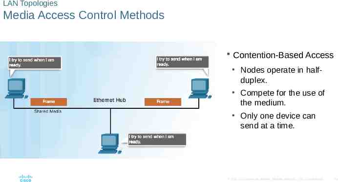
LAN Topologies Media Access Control Methods Contention-Based Access Nodes operate in halfduplex. Compete for the use of the medium. Only one device can send at a time. 2016 Cisco and/or its affiliates. All rights reserved. Cisco Confidential 69
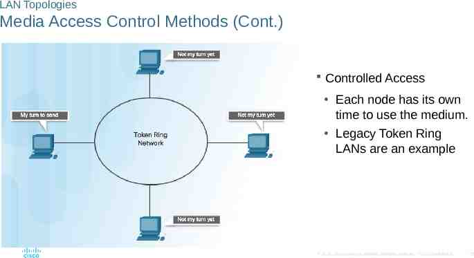
LAN Topologies Media Access Control Methods (Cont.) Controlled Access Each node has its own time to use the medium. Legacy Token Ring LANs are an example 2016 Cisco and/or its affiliates. All rights reserved. Cisco Confidential 70
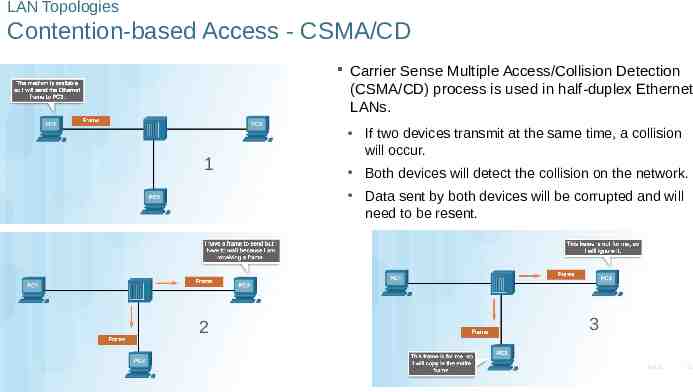
LAN Topologies Contention-based Access - CSMA/CD Carrier Sense Multiple Access/Collision Detection (CSMA/CD) process is used in half-duplex Ethernet LANs. 1 If two devices transmit at the same time, a collision will occur. Both devices will detect the collision on the network. Data sent by both devices will be corrupted and will need to be resent. 2 3 2016 Cisco and/or its affiliates. All rights reserved. Cisco Confidential 71
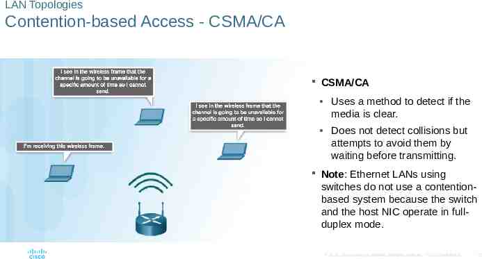
LAN Topologies Contention-based Access - CSMA/CA CSMA/CA Uses a method to detect if the media is clear. Does not detect collisions but attempts to avoid them by waiting before transmitting. Note: Ethernet LANs using switches do not use a contentionbased system because the switch and the host NIC operate in fullduplex mode. 2016 Cisco and/or its affiliates. All rights reserved. Cisco Confidential 72
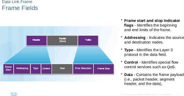
Data Link Frame The Frame Each frame type has three basic parts: Header Data Trailer Structure of the frame and the fields contained in the header and trailer depend on Layer 3 protocol. 2016 Cisco and/or its affiliates. All rights reserved. Cisco Confidential 73
Data Link Frame Frame Fields Frame start and stop indicator flags - Identifies the beginning and end limits of the frame. Addressing - Indicates the source and destination nodes. Type - Identifies the Layer 3 protocol in the data field. Control - Identifies special flow control services such as QoS. Data - Contains the frame payload (i.e., packet header, segment header, and the data). 2016 Cisco and/or its affiliates. All rights reserved. Cisco Confidential 74
Data Link Frame Layer 2 Addresses Each data link frame contains the source data link address of the NIC card sending the frame, and the destination data link address of the NIC card receiving the frame. 2016 Cisco and/or its affiliates. All rights reserved. Cisco Confidential 75
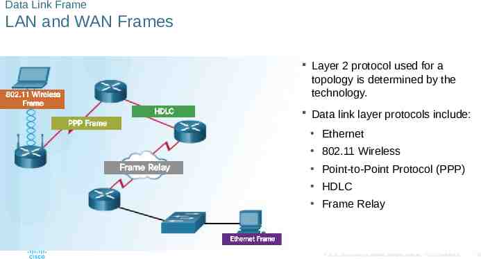
Data Link Frame LAN and WAN Frames Layer 2 protocol used for a topology is determined by the technology. Data link layer protocols include: Ethernet 802.11 Wireless Point-to-Point Protocol (PPP) HDLC Frame Relay 2016 Cisco and/or its affiliates. All rights reserved. Cisco Confidential 76
4.5 Chapter Summary 2016 Cisco and/or its affiliates. All rights reserved. Cisco Confidential 77
Conclusion Chapter 4: Network Access Explain how physical layer protocols and services support communications across data networks. Build a simple network using the appropriate media. Explain the role of the data link layer in supporting communications across data networks. Compare media access control techniques and logical topologies used in networks. 2016 Cisco and/or its affiliates. All rights reserved. Cisco Confidential 78